3D-4 Propeller Shafts:
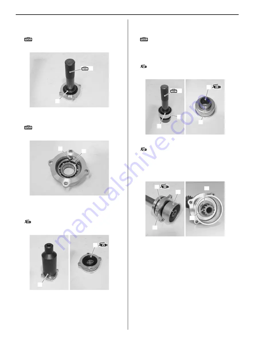
2) Install the front output shaft bearing (front) (2) to the
front output shaft housing with the special tool.
Special tool
(A): 09913–70210 (Bearing installer set (10
– 75))
3) Install the washer (3) and snap ring (4).
Special tool
: 09900–06108 (Snap ring remover (Close
type))
4) Install the oil seal (5) with the suitable socket
wrench.
5) Apply grease to the lip of oil seal (5).
: Grease 99000–25160 (Water resistance
grease or equivalent)
6) Install the front drive collar (6) to the output oil seal
plate (7) with the special tool.
Special tool
(A): 09913–70210 (Bearing installer set (10
– 75))
7) Install the O-ring (8) to the front drive collar (6).
8) Apply grease to the O-ring (8).
: Grease 99000–25010 (SUZUKI SUPER
GREASE A or equivalent)
9) Install the O-ring (9) and apply grease to it.
: Grease 99000–25010 (SUZUKI SUPER
GREASE A or equivalent)
10) Install the front output shaft housing (10) and front
drive collar assembly (11) to the front output shaft.
11) Install the snap ring (12) and C-ring (13).
(A)
2
I931H1340015-01
3
4
I931H1340016-01
5
5
I931H1340017-02
(A)
6
7
6
8
I931H1340018-01
9
10
11
12
13
I931H1340019-01
Summary of Contents for 2009 LT-A500XP
Page 2: ......
Page 4: ......
Page 14: ...00 9 Precautions ...
Page 224: ...1E 3 Engine Lubrication System EXHAUST SIDE INTAKE SIDE I931H1150003 02 ...
Page 304: ...1K 4 Exhaust System ...
Page 346: ...2D 5 Wheels and Tires ...
Page 438: ...3D 26 Propeller Shafts ...
Page 482: ...4D 6 Parking Brake ...
Page 512: ...5A 28 Automatic Transmission ...
Page 624: ...Prepared by December 2008 Part No 99500 44080 03E Printed in U S A 624 ...


