Rear Brakes: 4C-3
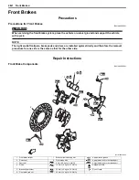
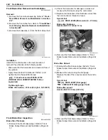
• Install the return spring (3) and lining indicator (4).
NOTE
Align the boss of lining indicator (4) with
wide spline on the brake cam shaft.
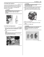
• Install the rear brake cam lever (5) to the rear brake
cam shaft.
NOTE
When installing the brake cam lever, align the
punched mark “D” with “E”.
• Tighten the cam lever nut (6) to the specified torque.
Tightening torque
Rear brake cam lever nut (b): 11 N·m (1.1 kgf-m,
8.0 lbf-ft)
• Install the final gear assembly. Refer to
“Final Gear
Assembly Removal and Installation: in Section
3B”
.
Rear Brake Disassembly and Assembly
B931H24306005
Refer to “Rear Brake Assembly Removal and Installation
(Page 4C-2)”.
Disassembly
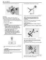
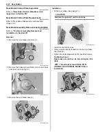
1) Remove the gasket (1) and dowel pins (2).
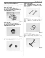
2) Remove the rear brake plates (3).
3) Remove the rear brake pressure plate (4) and balls.
4) Remove the rear bake cam shaft (5).
3
4
I831G1430008-01
1
(b)
6
“D”
“E”
I931H1430024-02
1
2
2
I931H1430005-01
3
I931H1430006-01
4
I931H1430007-02
5
I931H1430008-02
Summary of Contents for 2009 LT-A500XP
Page 2: ......
Page 4: ......
Page 14: ...00 9 Precautions ...
Page 224: ...1E 3 Engine Lubrication System EXHAUST SIDE INTAKE SIDE I931H1150003 02 ...
Page 304: ...1K 4 Exhaust System ...
Page 346: ...2D 5 Wheels and Tires ...
Page 438: ...3D 26 Propeller Shafts ...
Page 482: ...4D 6 Parking Brake ...
Page 512: ...5A 28 Automatic Transmission ...
Page 624: ...Prepared by December 2008 Part No 99500 44080 03E Printed in U S A 624 ...


