6B-7 Steering / Handlebar:
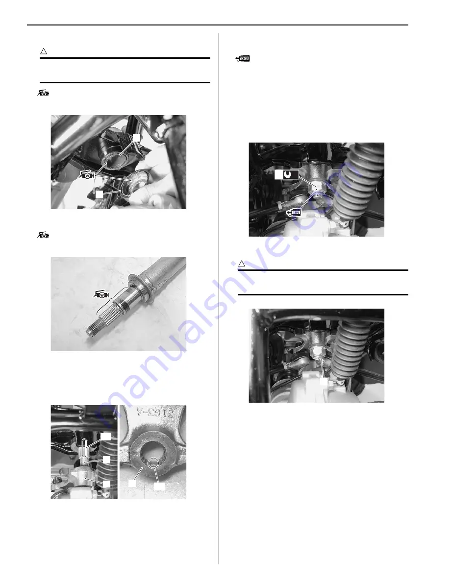
• Apply grease to the lower dust seal (3) and O-ring (4).
CAUTION
!
The removed O-ring must be replaced with a
new one.
: Grease 99000–25160 (Water resistance
grease)
• Apply grease to the steering shaft.
: Grease 99000–25160 (Water resistance
grease)
• Install the steering shaft.
• When installing the steering arm plate (5), align the
wide spline “A” of steering shaft (6) with the wide
spline “B” of steering arm plate (5).
• Apply a small quality thread lock to the thread part of
steering shaft.
: Thread lock cement 99000–32030
(THREAD LOCK CEMENT SUPER 1303 or
equivalent)
• Tighten the steering shaft lower nut (7) to the specified
torque.
Tightening torque
Steering shaft lower nut (a): 162 N·m (16.2 kgf-m,
117.0 lbf-ft)
• Install the cotter pin (8).
CAUTION
!
The removed cotter pin (8) must be replaced
with a new one.
• Install EPS body assembly. Refer to
“EPS Body
Assembly Removal and Installation: in Section
6C”
.
• Install the EPS control unit. Refer to
“EPS Control
Unit Removal and Installation: in Section 6C”
.
• Install the handlebars. Refer to “Handlebars Removal
and Installation (Page 6B-3)”.
• Install the front fender. Refer to
“Front Side Exterior
Parts Removal and Installation: in Section 9D”
.
• Install the front wheels. Refer to
“Front / Rear Wheel
Removal and Installation: in Section 2D”
.
• After installing these parts, adjust the toe. Refer to
“Toe Adjustment: in Section 0B”
.
4
3
I931H1620023-01
I931H1620024-03
6
5
“A”
“B”
5
I931H1620025-03
(a)
7
I931H1620026-02
8
I931H1620027-01
Summary of Contents for 2009 LT-A500XP
Page 2: ......
Page 4: ......
Page 14: ...00 9 Precautions ...
Page 224: ...1E 3 Engine Lubrication System EXHAUST SIDE INTAKE SIDE I931H1150003 02 ...
Page 304: ...1K 4 Exhaust System ...
Page 346: ...2D 5 Wheels and Tires ...
Page 438: ...3D 26 Propeller Shafts ...
Page 482: ...4D 6 Parking Brake ...
Page 512: ...5A 28 Automatic Transmission ...
Page 624: ...Prepared by December 2008 Part No 99500 44080 03E Printed in U S A 624 ...


