6C-16 Power Assisted Steering System:
9
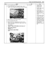
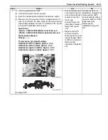
1) Turn the ignition switch ON with the EPS control unit
coupler disconnected, measure the voltage between
terminal “A” and terminal “B” at the coupler.
Special tool
(A): 09900–25008 (Multi-circuit tester set)
Tester knob indication
Voltage (
)
Normal value (“A” – “B”)
1.0 V and more
EPS control unit coupler (Vehicle harness end)
Is the voltage between “A” and “B” normal?
Go to Step 10.
Inspect the wire
harness. (Faulty
indicator light wire)
Step
Action
Yes
No
“A”
“B”
(A)
(A)
(
ޓ
)
(–)
I931H1630025-01
Summary of Contents for 2009 LT-A500XP
Page 2: ......
Page 4: ......
Page 14: ...00 9 Precautions ...
Page 224: ...1E 3 Engine Lubrication System EXHAUST SIDE INTAKE SIDE I931H1150003 02 ...
Page 304: ...1K 4 Exhaust System ...
Page 346: ...2D 5 Wheels and Tires ...
Page 438: ...3D 26 Propeller Shafts ...
Page 482: ...4D 6 Parking Brake ...
Page 512: ...5A 28 Automatic Transmission ...
Page 624: ...Prepared by December 2008 Part No 99500 44080 03E Printed in U S A 624 ...


