Fuel System: 1G-8
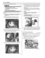
3) First, check for insulation with the tester between
terminals “A” and “B”. Next, check for continuity
between “A” and “B” with 12 V voltage applied,
positive (+) to terminal “C” and negative (–) to
terminal “D”. If continuity does not exist, replace the
relay with a new one.
Special tool
: 09900–25008 (Multi-circuit tester set)
Tester knob indication
Continuity test (
)
Fuel Hose Inspection
B831G21706005
Refer to “Fuel Line Inspection in Section 0B (Page 0B-
10)”.
Fuel Feed Hose Removal and Installation
B831G21706006
Removal
1) Remove the rear fender. Refer to “Rear Side Exterior
Parts Removal and Installation in Section 9D
(Page 9D-9)”.
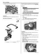
2) Disconnect the fuel feed hose (1).
Installation
1) Install the fuel feed hose as shown in the fuel hose
routing diagram. Refer to “Fuel Hose Routing
Diagram (Page 1G-3)”.
2) Install the rear fender. Refer to “Rear Side Exterior
Parts Removal and Installation in Section 9D
(Page 9D-9)”.
Fuel Level Gauge Inspection
B831G21706007
Refer to “Fuel Level Gauge Inspection in Section 9C
(Page 9C-6)”.
Fuel Level Indicator Inspection
B831G21706008
Refer to “Fuel Level Indicator Inspection in Section 9C
(Page 9C-5)”.
Fuel Tank Removal and Installation
B831G21706009
Removal
WARNING
!
• Keep away from fire or spark.
• Spilled gasoline should be wiped off
immediately.
• Work in a well-ventilated area.
1) Remove the rear fender. Refer to “Rear Side Exterior
Parts Removal and Installation in Section 9D
(Page 9D-9)”.
2) Remove the fuel tank outer cover. Refer to “Rear
Side Exterior Parts Removal and Installation in
Section 9D (Page 9D-9)”.
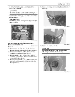
3) Place a rag under the fuel feed hose and disconnect
the fuel feed hose (1) from the fuel pump.
4) Disconnect the fuel tank coupler (2) and fuel tank
breather hose (3).
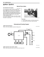
5) Remove the fuel tank mounting bolts.
6) Remove the fuel tank from the left side.
“A”
“B”
“C”
“D”
I718H1170013-01
1
I831G1170014-01
3
2
1
I831G1170015-01
I831G1170016-01
Summary of Contents for 2009 LT-A750XK9
Page 2: ......
Page 4: ......
Page 5: ...SUPPLEMENTS L LT A750XK9 09 MODEL 10 LT A750XPK9 09 MODEL 11 ...
Page 29: ...0A 15 General Information 99565 01010 013 CD ROM Ver 13 ...
Page 57: ...0B 28 Maintenance and Lubrication 09915 40610 Oil filter wrench Page 0B 12 Page 0B 12 ...
Page 68: ...0C 11 Service Data ...
Page 310: ...1K 5 Exhaust System ...
Page 482: ...4D 6 Parking Brake ...
Page 528: ...6B 13 Steering Handlebar ...
Page 581: ......

