background image

POWER UNIT     6-15

DISASSEMBLY

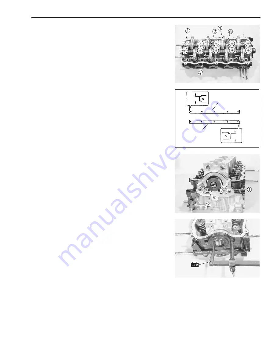
1. Remove the ten screws 

1

.

2. Remove the intake rocker arm shaft 

2

 and the exhaust rocker

arm shaft 

3

.

3. Remove all rocker arms 

4

 and all springs 

5

.

NOTE:
The intake rocker arm shaft differs from the exhaust one in shape
as shown.

4. Remove the two bolts 

1

 and the camshaft thrust plate 

2

.

5. Remove the oil seal using the special tool.

$

09913-50121: Oil seal remover

6. Remove the camshaft pulling toward the pulley side.

Intake

Exhaust

Pulley
side

Summary of Contents for DF 60

Page 1: ...9 9 5 0 0 9 9 E 1 0 0 1 E For 03 model ...

Page 2: ...r the engine unsafe for the boat operator and passengers FOREWORD This manual has been prepared using the lat est information available at the time of publi cation If a modification has been made since then differences may exist between the content of this manual and the actual outboard motor Illustrations in this manual are used to show the basic principles of operation and work pro cedures and m...

Page 3: ...tion easily 4 The first page of each section lists a table of con tents to easily locate the item and page you need COMPONENT PARTS AND IMPORTANT ITEM ILLUSTRATIONS Under the name of each system or unit an exploded view is provided with work instructions and other service information such as the tightening torque lubrication and locking agent points Example 1 Bolt 1 2 Washer 1 3 Key 1 4 Flywheel 1...

Page 4: ...THREAD LOCK 1342 Apply THREAD LOCK SUPER 1333B Measure in DC voltage range Measure in resistance range Measure in continuity test range Use peak voltmeter Stevens CD 77 Use special tool Torque control required Data beside it indicates specified torque Apply oil Use engine oil unless otherwise specified Apply SUZUKI OUTBOARD MOTOR GEAR OIL ApplySUZUKISUPERGREASE A Apply SUZUKI WATER RESISTANT GREAS...

Page 5: ...1 4 ENGINE OIL 1 4 ENGINE BREAK IN ________________________________________ 1 5 WARM UP RECOMMENDATION 1 5 THROTTLE RECOMMENDATION 1 5 PROPELLERS ____________________________________________ 1 6 SPECIFICATIONS _________________________________________ 1 7 SERVICE DATA ___________________________________________ 1 9 TIGHTENING TORQUE _____________________________________ 1 15 SPECIAL TOOLS ________...

Page 6: ...gether pay attention to the safety of each other When it is necessary to run the outboard motor indoors make sure that exhaust gas is vented outdoors When testing an outboard motor in the water and on a boat ensure that the necessary safety equipment is on board Such equipment includes flotation aids for each person fire extin guisher distress signals anchor paddles bilge pump first aid kit emerge...

Page 7: ... bolts and nuts beginning with larger diameter and ending with smaller diameter Always tighten from inside to outside diagonally to the specified tightening torque Whenever you remove oil seals gaskets packing O rings locking washers locking nuts cot ter pins circlips and certain other parts as specified always replace them with new Also before installing these new parts be sure to remove any left...

Page 8: ... equivalent octane con tent may be used Allowable maximum blend of a single additive not combina tion 5 Methanol 10 Ethanol 15 MTBE If leaded gasoline is used engine damage may re sult Use only unleaded gasoline ENGINE OIL Use only oils that are rated SE SF SG SH or SJ under the API American Petroleum Institute classification system The viscosity rating should be SAE 10W 40 If an SAE 10W 40 motor ...

Page 9: ...ngine speed for an extended period at any time during the engine break in by varying the throttle position occasionally 1 FIRST 2 HOURS For first 15 minutes operate the engine in gear at idling speed During the remaining 1 hour and 45 minutes operate the engine in gear at less than 1 2 half throttle 3000 r min NOTE The throttle may be briefly opened beyond the recommended setting to plane the boat...

Page 10: ...1300 3 13 15 V1500 VS1500 3 13 17 V1700 VS1700 3 13 19 V1900 VS1900 3 13 21 V2100 VS2100 If the standard propeller fails to meet the above requirement use another pitch propeller to hold the engine speed within the range specified above Propeller selection chart Recommended full throttle speed range DF60 4700 5300 r min DF70 5200 5800 r min Installing a propeller with pitch either too high or too ...

Page 11: ... 60 Recommended operating range r min Idle speed r min 51 5 70 4700 5300 5200 5800 700 50 in gear approx 700 POWERHEAD Engine type 4 stroke SOHC Number of cylinders 4 Bore mm in 74 0 2 91 Stroke mm in 75 5 2 97 Total displacement cm3 cu in 1298 79 2 Compression ratio 1 9 5 Spark plug NGK BPR6ES Ignition system Full transistorized ignition Fuel supply system Multi point sequential electronic fuel i...

Page 12: ...l filter change R M ml US Imp oz Gear oil Gearcase oil amounts SUZUKI Outboard Motor Gear Oil SAE 90 hypoid gear oil 1050 35 5 37 0 BRACKET Trim angle PTT system Number of trim position PTT system Maximum tilt angle 75 LOWER UNIT Reversing system Gear Transmission Forward Neutral Reverse Reduction system Bevel gear Gear ratio 12 29 2 417 Drive line impact protection Spline drive rubber hub Propell...

Page 13: ...in Limit Intake manifold seating faces distortion STD Limit mm in 37 961 1 4945 37 531 1 4776 IN mm in 38 059 38 219 1 4984 1 5047 37 629 37 789 1 4815 1 4878 STD Limit mm in 37 959 1 4944 37 529 1 4775 EX 0 050 0 091 0 0020 0 0036 mm in Camshaft journal oil clearance STD Limit 0 150 0 0059 mm in Camshaft holder inside diameter Top mm in STD 45 000 45 016 1 7717 1 7723 0 10 0 004 mm in Limit Camsh...

Page 14: ...stem outside diameter mm in STD STD mm in IN EX 6 965 6 980 0 2742 0 2748 6 940 6 955 0 2732 0 2738 IN EX mm in Limit 6 05 0 238 Valve stem end length Valve stem end deflection mm in Limit Limit mm in IN EX 0 14 0 006 0 18 0 007 IN EX mm in Limit 0 05 0 002 Valve stem runout IN EX mm in Limit 0 08 0 003 Valve head radial runout Valve head thickness mm in STD Limit mm in 1 0 0 04 0 6 0 02 mm in Lim...

Page 15: ...Piston measuring position 0 100 0 0039 mm in Limit Cylinder bore wear Piston ring free end gap mm in Approx 7 7 0 30 STD Limit mm in 6 1 0 24 1st mm in Approx 10 4 0 41 STD Limit mm in 8 3 0 33 2nd Piston ring groove width mm in 1 22 1 24 0 048 0 049 1st mm in 1 51 1 53 0 059 0 060 mm in 2 81 2 83 0 111 0 112 2nd Oil Piston ring to groove clearance mm in 0 03 0 07 0 001 0 003 STD Limit mm in 0 12 ...

Page 16: ...Crank pin width Crankshaft journal oil clearance 0 016 0 036 0 0006 0 0014 mm in STD 0 060 0 0024 mm in Limit Crankshaft center journal runout 0 06 0 002 mm in Limit Crankcase bearing holder inside diameter 56 000 56 018 2 2047 2 2054 mm in STD Crankshaft journal outside diameter 51 982 52 000 2 0465 2 0472 mm in STD Crankshaft journal outside diameter difference 0 010 0 0004 mm in Limit Crankshaf...

Page 17: ...lay resistance Ω at 20 C Starter motor relay resistance Ω at 20 C PTT motor relay resistance 1 8 2 3 80 120 3 5 5 1 3 0 4 5 168 252 1 9 2 5 No 2 No 3 15 26 including H T cord and spark plug cap No 1 No 4 16 28 including H T cord and spark plug cap BPR6ES 0 3 0 5 300 11 0 16 6 4 8 7 2 k Ω m at 20 C High tension cord resistance Approx 16 STARTER MOTOR 30 Sec Max continuous time of use 0 9 kW Motor o...

Page 18: ... 11 Fuel injector Open circuit 4 3 NO on off on off on off on off on off on off on off on off on off on off on off SELF DIAGNOSTIC SYSTEM INDICATION When the abnormality occurs in a signal from sensor switch etc the CHECK ENGINE lamp on the monitor tachometer flashes lights intermittently according to the each code pattern with buzzer sounding NOTE If more than two items fail at once the self diag...

Page 19: ... mm 23 2 3 16 5 Upper plug Lower union 10 mm 50 5 0 36 0 8 mm 73 7 3 53 0 Intake manifold bolt nut 12 mm Oil pump stopper 50 5 0 36 0 23 2 3 16 5 8 mm Exhaust manifold bolt nut 17 1 7 12 5 7 mm Valve adjusting lock nut 11 1 1 8 0 6 mm Rocker arm shaft screw 70 7 0 50 5 38 mm Timing pulley nut Oil regulator valve 27 2 7 19 5 14 mm Delivery pipe bolt 23 2 3 16 5 8 mm 12 mm 10 mm 50 5 0 36 0 Drivesha...

Page 20: ...0 6 1 0 4 5 7 0 8 mm 15 20 1 5 2 0 11 0 14 5 10 mm 34 41 3 4 4 1 24 5 29 5 5 mm 3 6 0 3 0 6 2 0 4 5 6 mm 8 12 0 8 1 2 6 0 8 5 8 mm 18 28 1 8 2 8 13 0 20 0 10 mm 40 60 4 0 6 0 29 0 43 5 Conventional or 4 marked bolt Tightening torque general bolt NOTE These values are only applicable when torque for a general bolt is not listed in the Important Fasteners table TYPE OF BOLT Stainless steel bolt 7 ma...

Page 21: ...80 mm 09900 20803 Thickness gauge 09900 28403 Hydrometer 09900 00411 Hexagon socket included in 09900 00410 09900 20202 Micrometer 25 50 mm 09900 20605 Dial calipers 10 34 mm 09900 21304 Steel V block set 09913 50121 Oil seal remover 09900 00413 5 mm 09900 00414 6 mm Hexagon bit included in 09900 00410 09900 20203 Micrometer 50 75 mm 09900 20602 Dial gauge 09900 22302 0 051 0 125 mm 09900 22301 0 ...

Page 22: ...ndle 09915 77311 Oil pressure gauge 09916 77310 Piston ring compressor 09915 78211 Oil pressure gauge adapter 44 35 09917 47011 Vacuum pump gauge 41 43 09916 84511 Tweezers 09922 89810 Shift lock pin remover 09916 24940 Solid pilot N 150 7 09916 34520 Valve guide reamer ø7 mm 09916 37310 Valve guide reamer ø12 mm 09916 44511 Valve guide remover installer 09916 57321 Valve guide installer 09917 882...

Page 23: ... 98221 Spacer 09930 30104 Sliding hammer 09930 76420 Timing light 09950 69512 Gearcase oil leakage tester 47 50 09930 39411 Flywheel rotor remover 54 55 09930 89240 4 pin connector test cord 09930 89260 Injector test cord A 58 59 SDS software ver 4 00 SDS database ver 4 10 No parts number 62 63 09940 44121 Air pressure gauge 09940 44130 Attachment 66 09951 09511 Gear adjusting gauge A B D C 99954 ...

Page 24: ... 99104 33140 99000 31140 100 g 99000 25160 250 g 99000 32050 50 g 99000 31120 50 g API SE SF SG SH SJ SAE 10W 40 SUZUKI SUPER GREASE A WATER RESISTANT GREASE SUZUKI SILICONE SEAL SUZUKI BOND 1207B THREAD LOCK 1342 4 Stroke Motor Oil NOTE Marked part No is in U S market only 70 NOTE Marked part No is in U S market only THREAD LOCK SUPER 1333B 99000 32020 50 g ...

Page 25: ...2 8 VALVE CLEARANCE 2 9 TIMING BELT 2 11 IDLE SPEED 2 14 IGNITION TIMING 2 15 BREATHER AND FUEL LINE 2 16 LOW PRESSURE FUEL FILTER 2 16 HIGH PRESSURE FUEL FILTER 2 16 WATER PUMP IMPELLER WATER PUMP 2 17 PROPELLER NUT AND PIN PROPELLER 2 17 ANODES AND BONDING WIRES 2 18 BATTERY 2 19 BOLTS AND NUTS 2 20 FUEL MIXTURE CHECK O2 FEEDBACK 2 21 OIL PRESSURE ___________________________________________ 2 23...

Page 26: ...nitial 20 hrs or 1 month Every 50 hrs or 3 months Every 100 hrs or 6 months Every 200 hrs or 12 months Spark plug I R Breather hose Fuel line I I I I Replace every 2 years Engine oil NOTE R R R Gear oil R R R Lubrication I I I Anodes Bonding wires I I I Battery I I I Fuel mixture check O2 feedback Perform every 2 years Engine oil filter Low pressure fuel filter Replace every 400 hours or 2 years H...

Page 27: ... level is low add the recommended oil to the full level hole Recommended oil 4 stroke motor oil API classification SE SF SG SH SJ Viscosity rating SAE 10W 40 Full level Low level 1 Place the outboard motor upright on a level surface 2 Remove the motor cover 3 Remove the oil level dipstick and wipe it clean 4 Insert the dipstick fully into the dipstick hole then pull it out 5 Oil level should be be...

Page 28: ...n replacing the engine oil filter change the engine oil at the same time 1 Place the outboard motor upright on a level surface 2 Remove the oil filler cap 3 Place an oil pan as shown then drain oil by removing the oil drain plug and the gasket NOTE For engine oil change only go to the STEP 7 4 Remove the port side cover See page 7 2 5 Remove the engine oil filter 09915 47340 Oil filter wrench 6 In...

Page 29: ...the oil change reminder system s operation time to zero cancellation 1 Turn the ignition key to the ON position 2 Pull out the emergency stop switch plate 1 3 Pull up the emergency stop switch knob 2 three times in 10 seconds A short beep will be heard if cancellation is successfully finished 4 Turn the ignition key to the OFF position 5 Set the emergency stop switch plate 1 in the orginal po siti...

Page 30: ... just starts to flow out from the oil level hole Gear oil amount 1050 ml 35 5 37 0 US Imp oz Recommended oil Suzuki Outboard Motor Gear Oil or SAE 90 Hypoid gear oil 5 Install the oil level plug before removing the oil filler tube from the drain hole 6 Install the oil drain plug Do not re use the gasket once removed Always use a new gasket NOTE To avoid insufficient injection of the gear oil check...

Page 31: ...NANCE 2 7 LUBRICATION Inspect every 50 hours 3 months Apply the Water Resistant Grease to the following points 99000 25160 Suzuki Water Resistant Grease Throttle linkage Propeller shaft Steering bracket Swivel bracket ...

Page 32: ...AP Measure for the spark plug gap using the thickness gauge Adjust to within the specified range if the gap is out of the speci fication Spark plug gap 0 7 0 8 mm 0 028 0 031 in 09900 20803 Thickness gauge CONDITION OF ELECTRODE INSULATOR Check the electrode and insulator condition If the electrode is extremely worn or burnt replace the spark plug If the spark plug has a broken insulator damaged t...

Page 33: ...heel clockwise to bring each piston to the Top Dead Center TDC on a compression stroke Align each PUNCH mark on the cam pulley with the INDEX mark on the cylinder head block PUNCH mark TDC cylinder number 1 No 1 cylinder 2 No 2 cylinder 3 No 3 cylinder 4 No 4 cylinder Rotate the crankshaft in the normal running direction only clockwise to prevent water pump impeller dam age NOTE The piston must be...

Page 34: ...he valve adjusting lock nut 1 while holding the valve adjusting screw 2 Valve adjusting lock nut 17 N m 1 7 kg m 12 5 lb ft 10 Recheck the valve clearance 11 Assembly in reverse order of disassembly with the special attention to the following steps Cylinder head cover bolt 10 N m 1 0 kg m 7 0 lb ft Do not re use the gasket once removed Always use a new gasket ADJUSTMENT 7 Loosen the valve adjustin...

Page 35: ...belt 1 Replace the following parts Flywheel cover Spark plugs Flywheel See the page 3 52 Battery charge coil See the page 4 4 09930 48720 Flywheel holder 09930 39411 Flywheel remover 09930 39420 Flywheel remover bolt 2 Remove the six bolts 3 Disconnect the wire 2 and the hose 3 from the MAP sen sor 4 Disconnect the wire 4 from the CKP sensor 5 Remove the bracket 1 ...

Page 36: ...be checked The PUNCH mark on the timing pulley aligns with the INDEX mark on the cylinder block The PUNCH mark 1 on the cam pulley aligns with the INDEX mark on the cylinder head block If the timing pulley or the cam pulley is rotated with the timing belt removed or installed but misaligned this may cause the valves to become bent If the alignment marks are not correctly matched loosen the valve a...

Page 37: ...ulley aligns with the INDEX mark on the cylinder head block when the PUNCH mark on the timing pulley aligns with the INDEX mark on the cylinder block 14 Lightly push the tensioner toward the belt then tighten the two bolts 15 Install the following parts Starter motor bracket Battery charge coil See page 4 5 Flywheel See page 3 52 Spark plugs Flywheel cover ...

Page 38: ...cation perform the following adjustment procedure 4 Check that the CTP switch is in the ON position 5 To set the IAC valve duty to constant 22 5 raise the engine speed to 1000 r min or higher by turning the by pass air screw and hold that speed for 10 seconds At this time the buzzer will sound to notify that the IAC duty is in the fixed mode Turning air screw counterclockwise Engine speed will inc...

Page 39: ...sage including the IAC hose may be clogged or the IAC system may not be operating correctly See the IDLE AIR CONTROL SYSTEM section on the page 3 21 NOTE The trolling speed in gear idle speed is the same as the idel speed IGNITION TIMING Inspect every 200 hours 12 months NOTE Before checking the ignition timing make sure that the idle speed is adjusted within the specification 1 Start and warm up ...

Page 40: ...nt leakage crack or other dam age is found replace the fuel filter HIGH PRESSURE FUEL FILTER Replace every 1000 hours Breather hose Low pressure fuel filter Fuel hose Separator to H filter Fuel hose L pump to Separator Fuel hose Connector to L filter Fuel hose 3 way joint to Separator Fuel hose 3 way joint to Delivery pipe Fuel hose L filter to L pump Fuel hose H filter to 3 way joint High pressur...

Page 41: ...und on the pump case or the under panel replace Do not re use the gasket once removed Always use a new gasket PROPELLER NUT AND PIN PROPELLER Inspect initially after 20 hours 1 month and every 100 hours 6 months thereafter Make sure that the propeller nut and the pin are installed se curely If excessive wear breakage or other damage is found on the propeller the propeller bush or the propeller sha...

Page 42: ...s corroded away replace the anode Never paint the anode NOTE The anode securing bolt should be covered with the Suzuki Sili cone Seal 99000 31120 Suzuki Silicone Seal BONDING WIRES If breakage or other damage is found replace the wire If rust or corrosion is found on the wire terminal clean it with solvent Anode ...

Page 43: ...out of reach of chil dren When checking or servicing battery disconnect the negative black cable Be careful not to cause a short circuit by allowing metal objects to contact battery posts and motor at the same time Wear approved eye protection Recommended battery 12 V 100 AH 360 kC or larger battery CONNECTING BATTERY Upon completion of the connection lightly apply grease to the battery terminals ...

Page 44: ...m eter 09900 28403 Hydrometer Battery solution specific gravity 1 28 at 20 C BOLTS AND NUTS Inspect initially after 20 hours 1 month and every 100 hours 6 months thereafter Check that all bolts and nuts listed below are tightened to their specified torque ITEM TIGHTENING TORQUE N m kg m lb ft Cylinder head cover bolt 10 1 0 7 0 Cylinder head bolt Power unit mounting bolt nut Clamp bracket shaft nu...

Page 45: ...el mixture check O2 feedback operation us ing the SDS refer to the SDS Operation Manual program ver sion 4 00 NOTE See the O2 FEEDBACK SYSTEM section on the page 3 35 be fore starting the O2 feedback operation Procedure To prevent any sudden boat movement the boat must be securely moored to the dock while the test wheel equipped engine is running in gear during the feedback test procedure 1 Remove...

Page 46: ...sensor must be completely covered as shown 4 Connect the diagnostic harness to both the O2 sensor con nector and the engine harness connector 09932 79910 Diagnostic harness 5 Connect the adapter to the diagnostic harness 09932 89910 Adapter 6 Install the starboard side cover NOTE Route the diagnostic harness through the clearance between the remote control cable holder plate and the side cover 7 I...

Page 47: ...min Winter 10 min at 2000 r min 7 After warming up shift into the forward gear and increase the engine speed to 3000 r min then compare the pressure indicated on the gauge to the specifications 8 Reinstall parts removed earlier OIL PRESSURE Oil pressure at normal operating temp 420 490 kPa 4 2 4 9 kg cm2 60 70 psi at 3000 r min NOTE The figure shown above is guideline only not absolute service lim...

Page 48: ... FUEL PRESSURE RELIEF PROCEDURE section on the page 5 2 CYLINDER COMPRESSION Cylinder compression 1300 1600 kPa 13 16 kg cm2 185 228 psi Max difference between any other cylinders 200 kPa 2 0 kg cm2 28 psi or less NOTE The figures shown above are guidelines only not absolute service limits Low compression pressure can indicate one or more of the following Excessively worn cylinder wall Worn piston...

Page 49: ...OW BATTERY VOLTAGE CAUTION SYSTEM 3 26 SELF DIAGNOSTIC SYSTEM ________________________________ 3 27 PRIORITY CODE PATTERN FOR SELF DIAGNOSTIC SYSTEM OPERATION 3 27 CONDITION FOR SELF DIAGNOSTIC SYSTEM OPERATION 3 29 FAIL SAFE SYSTEM _______________________________________ 3 30 PRE PROGRAMMED VALUE FOR FAIL SAFE SYSTEM 3 30 OPERATING HOUR INDICATION SYSTEM _____________________ 3 31 OIL CHANGE REMI...

Page 50: ...TP Closed throttle position IAC Idle air control INPUT sensor switch CONTROL ECM OUTPUT actuator etc Fuel injection control system IAT sensor Cylinder temp sensor Exhaust manifold temp sensor CTP switch Neutral switch O2 sensor optional MAP sensor CMP sensor CKP sensor Ignition control system Idle air control system Fuel pump control system Caution system Self diagnostic system Fail safe system Op...

Page 51: ...ensor O 2 sensor Exhaust manifold Spark plug Alternator Battery charge coil By pass air screw CTP switch IAT sensor Rectifier regulator Battery Ignition switch ECM main relay Engine control module Neutral switch Silencer cover Throttle body IAC valve Intake manifold Cylinder temp sensor CKP sensor Oil pressure switch Fuel injector Breather hose O 2 Sensor must be installed when performing O 2 feed...

Page 52: ...3 4 ENGINE CONTROL SYSTEM WIRING DIAGRAM FOR ENGINE CONTROL ENGINE CONTROL MODULE ...

Page 53: ...olling speed by adjusting intake air amount through IAC valve Fuel pump control Controls high pressure fuel pump drive Caution system control Informs operator of abnormal engine condition Controls engine speed Self diagnostic system control Informs operator of sensor switch malfunction Fail safe system control Allows operation during sensor switch malfunction Operating hour indication system contr...

Page 54: ...O Y PC communication 17 G Y TEMP lamp 18 19 20 B Ground for power souce 21 22 Lg No 4 Fuel injector 39 B Y No 2 Fuel injector 40 O B No 1 Fuel injector 41 42 B Ground for power source TERMI NAL WIRE COLOR CIRCUIT 23 Bl Oil pressure switch 24 Lg R CTP switch 25 P REV LIMIT lamp 26 G W CHECK ENGINE lamp 27 Bl W Buzzer 28 29 W MAP sensor 30 Gr ECM power source 31 Lg B IAT sensor 32 B Ground for ECM 3...

Page 55: ...ENGINE CONTROL SYSTEM 3 7 ECM INTERNAL STRUCTURE ...

Page 56: ...e During one crankshaft rotation 34 sig nals are supplied from the CKP sensor to the ECM CMP Camshaft Position SENSOR The CMP sensor is installed on the side of the camshaft pulley When the reluctor bars trigger vanes on the camshaft pulley passes the sensor signals voltage pulses are generated and sent to the ECM There are four trigger vanes on the camshaft pulley During one rotation of the camsh...

Page 57: ...tion timing etc CYLINDER TEMPERATURE SENSOR The cylinder temperature sensor is installed on the cylinder be hind the electric part holder and used to detect the cylinder tem perature This is a thermistor type sensor resistance of which changes depending on the temperature and inputs a signal to the ECM as a voltage value This input signal is used to compensate the fuel injection time duration igni...

Page 58: ...ming is fixed at BTDC 5 After shifting into forward or reverse from neutral the IAC valve is controlled to increase intake air for two seconds to prevent unstable engine idle or stalling CTP Closed Throttle Position SWITCH The CTP switch is installed on the bottom of throttle body and used to detect whether the throttle is fully closed or not This switch is ON at closed throttle and OFF at any ope...

Page 59: ...This detected voltage value therefore represents the oxygen con centration The terminal voltage decreases when the oxygen con centration is high and increases when it is low NOTE As the zirconia element is not conductive below 250 C the O2 sensor will not function properly until the engine is at normal operating temperature NOTE Zirconia element The zirconia element produces a potential difference...

Page 60: ...is composed of the ignition coil spark plug and components for system control ECM sensor switch etc When the ignition switch is ON battery voltage 12V is applied to the circuit as shown in the illustration At the calculated time of ignition the transistor in the ECM turns OFF breaking the grounded circuit In this way a mutual induction high voltage occurs in the ignition coil secondary side and sp...

Page 61: ...CONTROL MODE WHEN CRANKING The ignition timing is fixed at BTDC 5 until the engine starts WHEN IDLING TROLLING The ignition timing is controlled within the range of BTDC 4 to BTDC 16 to provide stable engine operation at the specified idling trolling speed When the shift lever is in neutral if engine speed exceeds 1000 r min ignition timing remains fixed at BTDC 5 WHEN RUNNING NORMAL OPERATION The...

Page 62: ...duration fuel amount fuel injection timing multi point sequential timing and controls the injector operating signals accordingly Fuel injection start timing is set at BTDC 484 on exhaust stroke constant Basic sensors Compensating sensors Injector MAP sensor Informs ECM of intake manifold pressure CKP sensor Informs ECM of engine speed and crankshaft angle Cylinder temperature sensor Informs ECM of...

Page 63: ...ap for altitude WHEN CRANKING Fuel is simultaneously injected to all cylinders every time any piston is positioned at compression stroke AFTER START FAST IDLE FUNCTION The fuel injection amount is controlled to increase until the timer set according to cylinder temperature at the time of engine start expires WHEN IDLING TROLLING The fuel injection amount is controlled to maintain a stable engine s...

Page 64: ... the primer bulb low pressure fuel filter and low pressure pump to the fuel vapor separator Fuel flow from the fuel vapor separator is pressurized by the high pressure fuel pump and supplied through the high pressure fuel filter and fuel delivery pipe to the fuel injectors The pressure regulator maintains fuel pressure in the feed line between the high pressure fuel pump and fuel injector This pre...

Page 65: ...e fuel level decreases fuel flows into the vapor separator from the low pressure fuel pump The function of this unit is to separate vapors from fuel delivered by the low pressure fuel pump or fuel returned from the fuel pressure regulator This vapor is routed through the evaporation hose connecting the vapor separator cover to the silencer cover HIGH PRESSURE FUEL PUMP The high pressure fuel pump ...

Page 66: ...approx 255 kPa 2 55 kg cm2 36 3 psi By pass fuel is returned back to the fuel vapor separator chamber FUEL INJECTOR The fuel injector is an electromagnetic valve operated by a sig nal from the ECM When the injection signal is supplied to the fuel injector the so lenoid coil is energized pulling up the plunger This opens the injector valve and injects fuel Because the fuel pressure is kept constant...

Page 67: ... second Based on engine speed and battery voltage the ECM determines the optimum duty repeating ON time rate within a cycle and sends this signal to the fuel pump CONTROL MODE BEFORE START For 3 seconds after ignition switch is turned ON the pump is controlled to operate at 100 duty in order to initially pressurize the high pressure line WHEN CRANKING The pump is controlled to operate at 100 duty ...

Page 68: ...fully closed the main supply of intake manifold air necessary to sustain the engine idle passes through the by pass air passage To maintain the engine idle speed at the specification the ECM controlled the IAC valve supplies a regulated amount of additional air through the IAC idle air control passage THROTTLE BODY The throttle body adjusts the intake air amount with the throttle valve which is co...

Page 69: ...from the ECM IDLE AIR CONTROL SYSTEM OUTLINE The ECM controls the duty cycle signal of the IAC valve to regulate a portion of the intake air flow to the intake manifold This system is used for the following purposes To keep idling trolling at the specified speed To improve driveability when decelerating Dash pot effect To improve engine starting and warm up performance Fast idle function The senso...

Page 70: ... conditions change WHEN RUNNING NORMAL OPERATION The IAC valve is controlled to operate at 20 100 duty which depends on the current engine conditions WHEN DECELERATING DASH POT EFFECT When the throttle valve is suddenly returned to full close and the CTP switch signal changes to ON the IAC valve operates at a controlled gradual return to idle troll operating duty to prevent engine stalling or unst...

Page 71: ...s 1 No Yes Low oil pressure Yes 2 1 Yes Yes Overheat Yes 3 1 Yes Yes Yes 4 Yes No Low battery voltage 1 REV LIMIT lamp 2 OIL lamp 3 TEMP lamp 4 CHECK ENGINE lamp MONITOR TACHOMETER OVER REVOLUTION CAUTION SYSTEM CONDITION When the engine speed exceeds 6500 r min the ECM initiates intermittent fuel injection and ignition signals to provide a maximum engine speed of 6500 r min Over revolution limite...

Page 72: ...s of long 1 5 sec beeps Engine speed Caution lamp Caution buzzer RESET Stop the engine and check the engine oil level Refill the engine oil to the correct level if below the low oil mark If the engine oil level is correct the following causes may be considered Improper oil viscosity Malfunctioning oil pressure switch Clogged oil strainer or oil filter Worn oil pump relief valve Oil leakage from oi...

Page 73: ...ure range Temperature difference 86 C 99 C Approx 2 2 C 99 C Approx 0 6 C Temperature range Temperature difference 80 C 95 C Approx 9 6 C 95 C Approx 1 4 C RESET Close the throttle to reduce the engine speed below approx 3000 r min When the cylinder temperature drops below the limits as shown below the system resets However the system may be activated again unless the cause for overheat such as in...

Page 74: ...gine speed limiter is activated Caution lamp CHECK ENGINE lamp lights continuously Caution buzzer Sounds in a series of long 1 5 sec beeps RESET This caution system is automatically reset when the battery voltage increases to more than 9 volts Refrain from using electrical equipments requiring high amperage such as hydraulic trim tabs hydraulic jack plate etc after this caution is activated ...

Page 75: ...ly canceled by pushing the ignition key in Remote con trol model only NOTE On the tiller handle model alerts is signaled by a sound sequence only from the buzzer contained in the tiller handle PRIORITY CODE PATTERN FOR SELF DIAGNOSTIC SYSTEM OPERATION PRIORITY FAILED ITEM CODE LAMP FLASHING PATTERN FAIL SAFE SYSTEM ACTIVE 1 MAP sensor 1 3 4 on off YES 2 CKP sensor 4 2 on off YES 3 IAC valve By pas...

Page 76: ... cylinder temp sensor the exhaust manifold temp sensor or the IAT sensor the self diagnostic indication will be canceled after corrective action by turning the ignition switch ON The ECM will require 10 20 seconds after turning the ignition switch ON to cancel the self diagnostic indication NOTE 1 The self diagnostic indication may be canceled by turning ignition switch ON because the ECM detects ...

Page 77: ... IAC valve By pass air screw adjustment No signal from CKP sensor while receiving 3 signals from CMP sensor No signal With engine running Receiving an out of range 37 860 mmHg 0 20 4 53 V signal With engine running IAC valve operates at 90 duty or higher when CTP switch is ON NOTE 1 No signal from CMP sensor while receiving 544 signals from CKP sensor Corresponded to 16 turns of crankshaft Receivi...

Page 78: ...as failed NOTE 1 This value will change according to the current engine speed MAP sensor 1 319 475 mmHg Correspond to approx 750 4000 r min NOTE1 CKP sensor Based on signals from CMP sensor Ignition timing fixed at BTDC 5 Normal sequential fuel injection CMP sensor Based on signals from CKP sensor a Failed while engine running Ignition timing fixed at BTDC 5 Normal sequential fuel injection b Fail...

Page 79: ... The total operating hours displayed are those of actual engine operation not ignition switch ON time CHART OF TOTAL OPERATING HOURS INDICATION Total operating hours MONITOR TACHOMETER Needle 1 1 1 1 1 indication REV LIMIT lamp 2 2 2 2 2 flashing 0 h 49 h 50 h 60 h No 540 h 550 h 560 h 1 time 1040 h 1050 h 2 times 1540 h 1550 h 3 times 2030 h 2040 h or over 3 times MONITOR TACHOMETER No 500 rpm 60...

Page 80: ... indication will repeat until canceling sys tem activation NOTE This system will activate up to 2100 hour s operation INDICATION OF SYSTEM ACTIVATION 1 Lapse of initial 20 hour s operation 2 Lapse of 80 hour s operation 3 Lapse of 100 hour s operation 4 When performing cancellation before system activation Buzzer OIL lamp NOTE On the tiller handle model the buzzer for system activation will first ...

Page 81: ...finished 4 Turn the ignition key to the OFF position 5 Set the switch plate 1 in the original position NOTE Canceling of the system activation is possible regardless of whether or not the engine oil has been replaced Once the system has operated however Suzuki strongly recommends that the engine oil be replaced before canceling the system activation Even if the engine oil has been replaced with th...

Page 82: ...block starboard side and operated by the clutch control arm This ON OFF type switch is ON in neutral and OFF in forward or reverse On starting the engine the ECM detects the shift position using the neutral switch When the neutral switch is OFF the ECM does not provide injector operating signal This neutral switch is also used to regulate the starter motor circuit The engine will not start even by...

Page 83: ...in the exhaust manifold This sensor is used to measure the concentration of oxygen in the exhaust gas at engine speed of 2000 3000 and 4000 r min The ECM uses the input data from the O2 sensor to correct the compensation coefficient of the fuel injection duration map within the ECM itself NOTE See the FUEL MIXTURE CHECK O2 FEEDBACK section on the page 2 21 for the procedure of the O2 feedback oper...

Page 84: ...nd disconnect the battery cables when the wires are being disconnected or connected Hold and pull the connector pieces when disconnecting Do not pull the wires NOTE Self diagnostic codes will remain in the ECM memory even if the battery is disconnected As each terminal voltage is affected by the battery voltage use a full charged battery Make sure all ground points have good electrical contact Mak...

Page 85: ...wiring harness 09930 89950 44 pin test cord 09930 99320 Digital tester Tester range V DC voltage 1 Connect the 44 pin test cord between the ECM and the wire harness as shown in the figure 2 Turn the ignition switch ON 3 Connect the tester probe Black to the body ground and measure the voltage according to the CIRCUIT VOLTAGE TABLE ECM 44 pin test cord Black connector White connector Wire harness ...

Page 86: ... Fuel injector Approx 12V Ignition switch ON 23 Oil pressure switch Approx 5V While engine running Approx 0V Other than above Ignition switch ON 24 CTP switch Approx 5V Ignition switch ON throttle not fully closed Approx 0V Ignition switch ON throttle fully closed 25 REV LIMIT lamp 26 CHECK ENGINE lamp 27 Buzzer 28 29 MAP sensor 0 20 4 53V Ignition switch ON 30 ECM power source Approx 12V Ignition...

Page 87: ...RESISTANCE TABLE TERMINAL LAYOUT OF WIRE HARNESS CONNECTOR RESISTANCE TABLE ITEM TERMINAL NO FOR TESTER PROBE CONNECTION STANDARD RESISTANCE at 20 C CMP sensor 15 to 11 Ignition coil No 1 4 Primary 44 to 30 Ignition coil No 2 3 Primary 43 to 30 Fuel injector No 1 Fuel injector No 2 Fuel injector No 3 IAC valve Cylinder temperature sensor Exhaust manifold temp sensor 7 to 11 ECM main relay 13 to Te...

Page 88: ...minal connected to the battery positive ter minal and check for injector operating sound Injector operating sound Click Connecting the fuel injector to the battery positive for more than a few seconds may cause injector overheat ing and possible injector solenoid failure NOTE 1 Disconnect the remote control wire harness and connect the tester probe to the terminal A Gray wire NOTE 2 Measure resist...

Page 89: ...ds as shown then turn the ignition switch ON 2 Connect the tester probe Black to the starter motor relay right terminal connected to the battery positive terminal as shown 3 Connect the tester probe Red to each terminal Ignition coil Terminal No No 1 4 44 No 2 3 43 4 Crank the engine and measure voltage Ignition coil operating signal 6 10 V Injector Terminal No No 1 40 No 2 39 No 3 38 4 Crank the ...

Page 90: ...pin test cord 09930 99320 Digital tester Taster range V DC voltage 1 Remove the CMP sensor from the engine 2 Connect the test cord as shown then turn the ignition switch ON 3 Connect the tester probe Red to the terminal 33 4 Connect the tester probe Black to the terminal 11 or body ground 5 Measure voltage when steel tip of a screwdriver is brought near and then pulled away from the sensor tip A C...

Page 91: ... the MAP sensor mea sure the 29 terminal voltage See the page 3 36 and 3 37 MAP sensor output voltage change Negative pressure kPa kg cm2 mmHg 29 terminal voltage V 0 0 0 40 0 4 300 80 0 8 600 4 00 2 42 0 84 at 1013 hPa barometric pressure CTP SWITCH 09930 99320 Digital tester Tester range Continuity 1 Disconnect the CTP switch wire 2 Inspect continuity between the CTP switch terminal and the body...

Page 92: ...h function ECM MAIN RELAY 09930 99320 Digital tester Tester range Continuity 1 Disconnect the ECM main relay from the wire 2 Inspect continuity between the terminal 1 and 2 each time 12 V is applied Connect the positive side to the terminal 4 and the negative side to the terminal 3 ECM main relay function 12 V power Continuity Applied Yes Not applied No Be careful not to touch 12 V power supply wi...

Page 93: ...e the page 4 6 CHART1 SELF DIAGNOSTIC CODE 3 4 START Ignition switch ON Check 35 terminal voltage Is result OK See page 3 38 Ignition switch ON Check 29 terminal voltage Is result OK See page 3 38 Possible cause ECM failure Wire continuity connection failure YES YES ECM failure NO MAP sensor failure NO CHART2 SELF DIAGNOSTIC CODE 4 2 START Ignition switch OFF Check CKP sensor signal Is result OK S...

Page 94: ...O CHART4 SELF DIAGNOSTIC CODE 2 4 START Ignition switch ON Cranking Check CMP sensor resistance Is result OK See page 3 39 Possible cause ECM failure Wire continuity connection failure YES CMP sensor failure NO NOTE It will be possible to start the engine if the CMP sensor has failed CHART5 SELF DIAGNOSTIC CODE 2 2 START Ignition switch ON Check 24 terminal voltage Is result OK See page 3 38 Possi...

Page 95: ... sensor resistance Is result OK See page 3 39 Possible cause ECM failure Wire continuity connection failure YES IAT sensor failure NO CHART8 SELF DIAGNOSTIC CODE 3 2 START Individual check Check MAP sensor hose is in good condition connection Is result OK Ignition switch ON Check MAP sensor output voltage change Is result OK See page 3 43 YES YES MAP sensor hose failure NO MAP sensor failure NO Cy...

Page 96: ...use the ECM detects battery voltage NOTE1 It is difficult to check the rectifier regulator completely Before replacing with new one check if its ground point has good electrical contact START Ignition switch OFF Check exhaust manifold temp sensor resistance Is result OK See page 3 39 Possible cause ECM failure Wire continuity connection failure YES Exhaust manifold temp sensor failure NO CHART10 S...

Page 97: ...cause Failure of high pressure fuel system components NO ECM main relay failure YES Ignition switch ON Check 2 terminal voltage Is result OK See page 3 38 YES YES Cranking Check ignition spark using timing light P no 09930 76420 Is there light flashing Ignition switch OFF Check ignition primary coil resistance See page 3 39 Check ignition secondary coil resistance See page 3 42 Are results OK Powe...

Page 98: ... failure Wire continuity connection failure Failure of high pressure fuel system components Fuel injector clog stuck valve etc Fuel pressure regulator incorrect regulated pressure etc Fuel pump clogged suction filter leakage in tank etc Fuel filter clog etc Hose clog kink leakage etc NOTE1 If the neutral switch has failed while engine running the engine will tend to stall when shifting into gear I...

Page 99: ...TION FLYWHEEL CKP SENSOR CMP SENSOR 1 Flywheel bolt 1 2 Washer 1 3 Key 1 4 Flywheel magneto 1 5 CKP sensor 1 6 Bolt 1 7 CMP sensor 1 8 Screw 2 9 Spacer 1 09930 48720 Flywheel holder 09930 39411 Flywheel remover 09930 39420 Flywheel remover bolt ...

Page 100: ...wo screws and the CMP sensor INSTALLATION Installation is reverse order of removal with the special attention to the following steps Flywheel Clean the flywheel and crankshaft mating surfaces with clean ing solvent Apply engine oil lightly to the flywheel bolt before installing 09930 48720 Flywheel holder Flywheel bolt 190 N m 19 0 kg m 137 5 lb ft CKP sensor CMP sensor Apply the thread lock to th...

Page 101: ...e Blue 3 Remove the oil pressure switch from the cylinder block INSTALLATION Installation is reverse order of removal with the special attention to the following steps Oil pressure switch 13 N m 1 3 kg m 9 5 lb ft NOTE Prior to installation wrap the oil pressure switch thread with sealing tape If the sealing tape edge is bulged out from the thread cut off the excess ...

Page 102: ... 2 INSPECTION 4 2 REMOVAL INSTALLATION 4 4 ELECTRIC STARTER SYSTEM_______________________________ 4 6 OUTLINE 4 6 TROUBLESHOOTING 4 7 INSPECTION 4 8 STARTER MOTOR 4 10 ELECTRIC PARTS HOLDER _________________________________ 4 17 MONITOR TACHOMETER ___________________________________ 4 18 CONTENTS ...

Page 103: ...e phase AC current generated from the battery charge coil is converted by the rectifier regulator into regulated DC current which is used to charge the battery OUTPUT REGULATED VOLTAGE 300 W 14 5 15 5 V Battery charge coil Alternator Magneto HIC Rectifier regulator Battery 12V To Starter motor Starter motor relay 30A Fuse To PTT switch To ECM main relay To Ignition switch B Y Y Y W W W R Y Y Y ...

Page 104: ... Disconnect all wires of the rectifier regulator 2 Measure resistance between the terminals for all combina tions NOTE The values given below are for the SUZUKI digital tester As thyristors diodes etc are used inside this rectifier regula tor the resistance values will differ when an ohmmeter other than the SUZUKI digital tester is used Rectifier regulator resistance If the mesurement is out of th...

Page 105: ... the flywheel See page 3 52 2 Remove the three screws 3 Disconnect the battery charge coil lead wire Rectifier regulator 1 Remove the electric parts holder See page 4 17 2 Remove the two bolts 1 Bolt 1 2 Washer 1 3 Key 1 4 Flywheel 1 5 Battery charge coil 1 6 Screw 3 7 Rectifier regulator 1 8 Bolt 2 1 190 N m 19 0 kg m 137 5 Ib ft 2 3 4 5 6 7 8 ...

Page 106: ...CAL 4 5 INSTALLATION Installation is reverse order of removal with the special attention to the following step Battery charge coil Apply the thread lock to the coil securing screws 99000 32050 Thread Lock 1342 ...

Page 107: ...ed of the battery the starter motor the relay the neutral switches and the ignition switch To ECM main relay To Rectifier regulator 30A Fuse To ECM Neutral switch Neutral switch Remote control box Ignition switch Battery Starter motor M B W Br GND BATT START OFF ON START FREE PUSH Br Br W W W W W R B R B W Br Br Y G Y G Y G ...

Page 108: ... there click sound Measure voltage at terminal 2 while turning ignition switch at START It must be above 12 V Is result OK Measure voltage at terminal 3 while turning ignition switch START It must be above 12 V Is result OK Starter motor failure Sub cable failure Measure voltage at terminal 1 It must be above 12V Is result OK Check if 30A fuse is in good condition Is result OK Check ignition switc...

Page 109: ... same as IGNITION SWITCH section except for tester probe connection Inspect continuity between the Green wire and the Black wire Emergency stop switch function If the result is out of the specification replace the emergency stop switch NEUTRAL SWITCH Neutral switch in remo con box NOTE The steps for this inspection are the same as IGNITION SWITCH section except for tester probe connection Inspect ...

Page 110: ...m the starter motor relay Resistance check Tester range Ω Ω Ω Ω Ω Resistance Measure resistance between theYellow Green wire and the Black wire Starter motor relay resistance 3 5 5 1 Ω Ω Ω Ω Ω If the resistance is out of the specification replace the starter motor relay Function check Tester range Continuity Inspect continuity between the terminal 1 and 2 with momently applying 12 V power Connect ...

Page 111: ...ver 2 Remove the breather hose and the evaporation hose 3 Remove the bolt the fastening band and the silencer cover 4 Disconnect the lead wire connectors from the IAT sensor the IAC valve and the CTP switch 5 Disconnect the throttle linkage rod 6 Remove the flame arrester and the seal rubber 7 Remove the six silencer throttle body securing bolts ...

Page 112: ...er motor assy INSTALLATION Installation is reverse order of removal with the special attention to the following steps Install the starter motor and tighten the four starter motor mount ing bolts securely Starter motor mounting bolt 23 N m 2 3 kg m 16 5 Ib ft Install the silencer and the throttle body to the intake manifold with the six bolts first then tighten the two silencer bracket bolts ...

Page 113: ...over the stator and the rear cover 1 Front cover 1 2 Stopper ring 1 3 Pinion stopper 1 4 Spring 1 5 Pinion 1 6 Cover 1 7 Armature 1 8 Washer 2 9 Stator 1 10 Brush 1 11 Brush spring 2 12 Brush holder 1 13 Rear cover 1 14 Bolt 2 15 Washer 1 16 Washer 1 17 Circrip 1 18 Sub rear cover 1 19 Screw 2 ...

Page 114: ...o screws 1 and the sub rear cover 2 3 Remove the circlip 1 the washer 2 and 3 NOTE When installing set the thicker washer 3 to the circlip side 4 Remove the two bolts 1 5 Remove the rear cover 1 and the brush holder 2 6 Remove the two washers 3 from the armature shaft ...

Page 115: ...mutator outside diameter 09900 20101 Vernier calipers Commutator outside diameter Standard 33 0 mm 1 30 in Service limit 32 0 mm 1 26 in If the measurement exceeds the service limit replace the arma ture 7 Remove the front cover 1 and the stator 2 INSPECTION SERVICING Pinion Inspect the pinion If excessive wear or other damage is found replace the pin ion A Armature and Commutator 1 Inspect the co...

Page 116: ...ecified depth NOTE Remove all particles of mica and metal using compressed air Wear safety grasses when using compressed air Continuity Yes No No Armature core Commutator Shaft Brush Brushes Measure length of each brush 09900 20101 Vernier calipers Brush length Standard 17 0 mm 0 67 in Service limit 10 0 mm 0 39 in If the mesurement exceeds the service limit replace the brush If the result is out ...

Page 117: ...o avoid break ing brushes Apply the grease to the armature shaft and the shaft holes 99000 25010 Suzuki Super Grease A Align the front cover the stator and the rear cover with the alignment lines scribed earlier and assemble the starter mo tor Through bolt 4 0 N m 0 4 kg m 2 9 Ib ft Base plate Wear safety grasses when disassembling and reassem bling stopper ring Install the pinion the spring the p...

Page 118: ...e page 10 2 to 10 5 for check of wire routing 8 Remove the four bolts and the electric parts holder 6 Remove the ECM 1 7 Disconnect the following wires in the electric parts holder Connector of cylinder temp sensor Lg W B W Connector of ex manifold temp sensor V W B W Blue wire on oil pressure switch Connector of PTT motor relay P Connector of PTT motor relay Lbl Connector of battery charge coil Y...

Page 119: ...positive terminal and the Black wire to the negative terminal of the battery Battery terminal Terminal for battery connection Test cord Meter Lighting lamp Negative Bl G W Lamp 1 Negative W G Y Lamp 2 Negative Y Bl B Lamp 3 Positive R P Lamp 4 1 2 3 4 B Gr 12 V Battery P G W G Y Bl B 1 CHECK ENGINE 2 TEMP 3 OIL 4 REV LIMIT 12 V Battery 12 V Battery Bl W Y R 3 Check if the lamp lights when connecti...

Page 120: ...ION 5 4 FUEL VAPOR SEPARATOR HIGH PRESSURE FUEL PUMP _____ 5 6 REMOVAL INSTALLATION 5 6 DISASSEMBLY 5 7 INSPECTION 5 8 REASSEMBLY 5 9 FUEL INJECTOR DELIVERY PIPE ___________________________ 5 11 REMOVAL 5 11 INSPECTION 5 11 INSTALLATION 5 12 LOW PRESSURE FUEL PUMP _______________________________ 5 13 REMOVAL INSTALLATION 5 13 DISASSEMBLY REASSEMBLY 5 14 INSPECTION 5 15 FUEL TANK __________________...

Page 121: ...zed fuel systems To avoid potential fire hazards do not allow fuel to spill on hot engine parts or on operating electrical components Wipe up fuel spills immediately The components after the high pressure fuel pump remain pressurized at all times To protect against fuel spray relieve fuel line pressure before disconnecting or removing compo nents FUEL PRESSURE RELIEF PROCEDURE 1 Turn the ignition ...

Page 122: ...nts with engine either op erating or at rest Extreme care should be taken not to cut abrade or cause any other damage to hoses Use care not to excessively compress hoses when tightening clamps NOTE Check the fuel hose routing See the page 10 8 and 10 9 Check for fuel leakage FUEL LEAKAGE CHECK PROCEDURE After performing any fuel system service always be sure that there is not fuel leakage by check...

Page 123: ...art of the pipe by 20 30mm 0 8 1 2 in For the type C pipe hose should fit up against flanged part of the pipe For the type D pipe hose should cover the pipe by 20 30mm 0 8 1 2 in FUEL PRESSURE INSPECTION 1 Relieve the fuel pressure in line See the page 5 2 2 Remove the port side cover See the page 7 2 3 Remove the high pressure fuel filter from the intake mani fold 4 Connect the special tools betw...

Page 124: ...asure the fuel pressure in line at cranking or idle speed operation Fuel pressure Approx 255 kPa 2 55 kg cm2 36 3 psi 8 Stop the engine and wait 5 minutes 9 Read residual fuel pressure in line Residual fuel pressure 200 kPa 2 0 kg cm2 28 4 psi or higher As the fuel feed line is still under high fuel pressure make sure to release fuel pressure according to the following procedures Place container u...

Page 125: ...el line pressure before disconnecting or removing the components See the page 5 2 REMOVAL 1 Remove the intake manifold assembly See the page 6 2 2 Remove the four bolts and the fuel vapor separator assem bly from the intake manifold 3 Disconnect all hoses from the fuel vapor separator INSTALLATION Installation is reverse order of removal See the page 6 5 for installation of the intake manifold ass...

Page 126: ...uel pump from the separator case 3 Remove the float pin 1 and the float 2 4 Remove the needle valve 1 the screw 2 the plate 3 and the valve seat 4 5 Remove the plate 1 6 Remove the screw and the fuel pressure regulator 2 from the separator case 7 Remove the screw 1 8 Remove the suction filter 2 with the bracket ...

Page 127: ...s excessive wear or other damage is found on any com ponent replace component Needle valve Valve seat Inspect the needle valve and the valve seat for groove other dam age or dirt Replace or clean if necessary Float Inspect the float for crack or other damage Replace if necessary Filter Inspect the pump suction filter for clog or other damage Replace or clean if necessary ...

Page 128: ...240 270 kPa 2 4 2 7 kg cm2 34 1 38 4 psi If the result is out of the specification replace the regulator REASSEMBLY Assembly is reverse order of disassembly with the special at tention to the following steps High pressure fuel pump Connect the pump lead wire connector then install the grommet 1 and fuel pump 2 NOTE Apply fuel to the grommet before installing Float Float pin Install the float and t...

Page 129: ...ator 2 Install the plate Separator cover Separator case 1 Install the seal ring then apply the Suzuki Bond evenly to only the outside mating surface of the separator case as shown in the figure 99000 31140 Suzuki Bond 1207B NOTE Clean the mating surfaces before applying the bond Do not apply the bond to the seal ring the groove and the in side mating surface 2 Install the separator case then tight...

Page 130: ...pull the fuel feed hose from the fuel delivery pipe Drain any excess fuel in the hose into a small container INSPECTION See the page 3 39 to 3 41 for inspection of the fuel injector operation 3 Disconnect the four fuel injector connectors 4 Remove the two bolts and the fuel delivery pipe with the fuel injectors A small amount of fuel may be released when the fuel injector is removed from delivery ...

Page 131: ... Replace the injector cushion 3 with new one and install it to the cylinder head 4 Install the delivery pipe with the injectors into the cylinder head 5 Tighten the two delivery pipe bolts and make sure that the injectors rotate smoothly Fuel delivery pipe bolt 23 N m 2 3 kg m 16 5 lb ft 6 Reconnect the fuel feed hose to the fuel delirery pipe 7 Connect the lead wires to each injector connectors 8...

Page 132: ...stalling the fuel pump rotate the crankshaft to bring the No 1 top cylinder piston to the Top Dead Center on a compression stroke Do not re use the O ring once removed Always use a new O ring Low pressure fuel pump bolt 10 N m 1 0 kg m 7 0 lb ft REMOVAL INSTALLATION REMOVAL 1 Remove both side covers See the page 7 2 2 Disconnect the hose 1 inlet and the hose 2 outlet from the fuel pump 3 Remove th...

Page 133: ...the cut away of the pump body 0 Remove the following parts Piston 6 Spring 7 Diaphragm 8 Spring 9 Pump body 0 REASSEMBLY Reassembly is reverse order of disassembly with the special attention to the following step NOTE After connecting the diaphragm 1 to the piston 2 with the pin 3 align the six diaphragm holes to the pump body holes by turn ing the piston 2 and the diaphragm 1 together so that the...

Page 134: ...damage is found replace the fuel pump assembly Check valves Inspect the check valves in the valve body If tear distortion or other damage is found replace the fuel pump assembly Pump body Inspect the pump body If crack nick distortion or other dam age is found replace the fuel pump assembly ...

Page 135: ... 1 2 b Connector 1 3 Clip 4 4 Primer bulb 1 5 Tank cap 1 6 Gasket 1 7 Connector plug 1 8 Outlet 1 9 Filter 1 0 O ring 1 A Fuel tank 1 1 Tank cap 1 2 Gasket 1 3 Screw 4 4 Gasket 4 5 Connector plug 1 6 Gasket 1 7 Fuel gauge assy 1 8 Cover 1 9 Gasket 1 0 Lens 1 A Gasket 1 B Screw 2 C Float 1 D Push nut 1 E Gasket 1 F Fuel hose assy 1 G Connector 1 H Clip 4 I Connector 1 J Primer bulb 1 K Fuel tank 1 ...

Page 136: ... the check valve function is defective replace the bulb Fuel tank Inspect the fuel tank If crack leakage or deterioration is found replace the tank If water or other contamination is found drain and clean the tank Tank cap Check that the fuel tank vent opens and relieves internal tank pressure properly If vent is suspect replace the tank cap 1 2 1 2 1 Connector 2 Connector plug Fuel hose Inspect t...

Page 137: ...ION 6 10 CYLINDER HEAD ASSY __________________________________ 6 14 REMOVAL 6 14 INSTALLATION 6 14 DISASSEMBLY 6 15 INSPECTION SERVICING 6 17 REASSEMBLY 6 26 CYLINDER CRANKSHAFT PISTON _______________________ 6 28 DISASSEMBLY 6 28 INSPECTION SERVICING 6 32 REASSEMBLY 6 45 OPERATION ____________________________________________ 6 51 WATER COOLING SYSTEM 6 51 ENGINE LUBRICATION SYSTEM 6 52 CONTENTS ...

Page 138: ...he page 7 2 1 Remove the breather hose 2 and the evaporation hose 3 from the silencer cover 1 2 Remove the bolt the cover band and the silencer cover 3 Disconnect the fuel hoses from the low pressure fuel pump 4 Remove the two bolts and the high pressure fuel filter 5 Disconnect the fuel hose from the delivery pipe 6 Disconnect the wire from the fuel injectors 7 Remove the two bolts 8 Remove the d...

Page 139: ...emove the bolt and the low pressure fuel filter with the bracket 12 Disconnect the throttle rod 1 13 Remove the two bolts 2 14 Remove the two bolts securing front panel 15 Disconnect the wires from the CTP switch 1 the IAT sen sor 2 and the IAC valve 3 16 Disconnect the MAP sensor hose 4 from the intake mani fold ...

Page 140: ...wire from the high pressure fuel pump 19 Pull out the oil level gauge 1 20 Remove the bolt and the gauge guide 2 21 Disconnect the evaporation hose from the fuel vapor sepa rator 22 Remove the eight bolts and the three nuts 23 Remove the intake manifold assy ...

Page 141: ...the gaskets 2 Apply the thread lock to the two bolts as shown 99000 32050 THREAD LOCK 1342 Tighten the eight bolts and the three nuts according to the numerical order as shown Intake manifold bolt nut 25 N m 2 5 kg m 18 0 lb ft Install the fuel injector and the delivery pipe CHECKING Check hose routing See the page 10 8 to 10 12 Check wire routing See the page 10 2 to 10 7 Check for fuel leakage a...

Page 142: ...ee the page 6 2 1 Remove the electric parts holder See the page 4 17 2 Remove the two bolts and the rectifier regulator 3 Remove the screw and the cylinder temperature sensor 4 Disconnect the spark plug caps from the spark plug 5 Disconnect the wires from the ignition coils 6 Remove the four bolts and the ignition coils ...

Page 143: ... the page 4 4 9 Remove the CKP sensor and the CMP sensor See the page 3 52 10 Disconnect the MAP sensor wire 11 Remove the starter motor See the page 4 10 12 Remove the four bolts and the starter motor bracket 13 Remove the eight bolts the four nuts and the exhaust mani fold 14 Disconnect the water inspection hose 1 15 Disconnect the water hose from the water pressure valve cover 2 ...

Page 144: ...ont panel 19 Loosen the nut 2 and push the clutch shaft 1 toward the port side 20 Disconnect the shift rod 3 from the clutch shaft 21 Remove the bolt the throttle control lever 1 and the clutch control lever 2 22 Remove the two bolts and the neutral switch 3 with the bracket 23 Remove the low pressure fuel pump the O ring and the pump rod See the page 5 13 ...

Page 145: ...g screws 2 fully To prevent valve damage loosen the valve adjusting lock nuts and the valve adjusting screws fully before remov ing the timing belt 28 Remove the three bolts and timing belt tensioner 1 29 Remove the cam pulley bolt then remove the timing belt with the cam pulley See the page 2 12 30 Remove the side cover seal from the engine holder 31 Remove the ten bolts and the two nuts ...

Page 146: ...e gasket 2 Drive the locking edges of the lock washer 2 3 Remove the oil pump stopper 3 from the oil pan POWER UNIT INSTALLATION 1 Set the two dowel pins and the gasket 2 Apply the grease to the drive shaft splines 99000 25160 Suzuki Water Resistant Grease 3 Install the power unit to the engine holder NOTE Rotate the crankshaft to aid alignment of the drive shaft and the crankshaft splines INSTALL...

Page 147: ...ore engaging the oil pump shaft with the groove in the cam shaft 2 Engage the oil pump shaft with the groove in the camshaft by using a screw driver as shown While holding the screw driver tighten the oil pump stopper 1 Oil pump stopper 50 N m 5 0 kg m 36 0 lb ft 3 Bent two locking edges of the lock washer 1 toward the opposite direction each other upward and downward 4 Tighten the plug 2 with the...

Page 148: ...m 43 5 lb ft 4 Install the flywheel See the page 3 52 Flywheel bolt 190 N m 19 0 kg m 137 5 lb ft 09930 48720 Flywheel holder CYLINDER HEAD COVER 1 Install the gasket 1 on the cylinder head cover 2 Tighten the six bolts Cylinder head cover bolt 10 N m 1 0 kg m 7 0 lb ft NOTE Before installing the cylinder head cover adjust the valve clear ance See the page 2 9 WATER HOSE Install the water hoses NO...

Page 149: ...properly adjusted Fuel hose routing matches the service manual illustration See the page 10 8 to 10 10 Wire routing matches the service manual illustration See the page 10 2 to 10 7 No fuel leakage is evident No water leakage is evident during final test running INTAKE MANIFOLD FUEL INJECTOR DELIVERY PIPE 1 Install the intake manifold assy See the page 6 5 2 Install the fuel injector and the deliv...

Page 150: ...tall the cylinder head to the cylinder block 3 Apply engine oil lightly to the cylinder head bolts 4 Tighten the bolts to 50 percent of the specified torque according to the numerical order in the figure Cylinder head bolt 50 torque 1st step 37 N m 3 7 kg m 27 0 lb ft 5 Loosen all bolt to 0 N m 0 kg m 0 lb ft according to the reverse order 2nd step 6 Finally tighten the bolts to the specified torq...

Page 151: ...emove all rocker arms 4 and all springs 5 NOTE The intake rocker arm shaft differs from the exhaust one in shape as shown 4 Remove the two bolts 1 and the camshaft thrust plate 2 5 Remove the oil seal using the special tool 09913 50121 Oil seal remover 6 Remove the camshaft pulling toward the pulley side Intake Exhaust Pulley side ...

Page 152: ...7 Remove the valve cotters 1 while compressing the valve spring 8 Remove the valve spring retainer 2 the valve spring 3 and the valve 4 09916 14510 Valve lifter 09916 48210 Attachment 09916 84511 Tweezers NOTE Reassemble each valve and valve spring to their original posi tions ...

Page 153: ...r the head components Be careful not to scuff or nick the metal surfaces when decarboning Valve seat Check the valve seat If crack or other damage is found replace the cylinder head Cylinder head distortion Measure the cylinder head distortion gasketed surface at a to tal of 6 locations as shown 09900 20803 Thickness gauge Straight gauge Service limit 0 05 mm 0 002 in If the measurement exceeds th...

Page 154: ...on is found clean the water jacket CAMSHAFT Cam height Measure the cam height H 09900 20202 Micrometer Standard DF60 IN 38 061 38 221 mm 1 4985 1 5048 in EX 38 059 38 219 mm 1 4984 1 5047 in DF70 IN 37 631 37 791 mm 1 4815 1 4878 in EX 37 629 37 789 mm 1 4815 1 4878 in Service limit DF60 IN 37 961 mm 1 4945 in EX 37 959 mm 1 4944 in DF70 IN 37 531 mm 1 4776 in EX 37 529 mm 1 4775 in If the measure...

Page 155: ...ance measure the following items Camshaft journal outside diameter 5 locations Camshaft holder inside diameter 5 locations 09900 20202 Micrometer Small bore gauge or Dial calipers Standard Camshaft journal Camshaft holder outside diameter inside diameter 44 925 44 950 mm 45 000 45 016 mm 1 7687 1 7697 in 1 7717 1 7723 in 44 725 44 750 mm 44 800 44 816 mm 1 7608 1 7618 in 1 7638 1 7644 in 44 525 44...

Page 156: ...e service limit replace the rocker arm shaft Rocker arm shaft to rocker arm clearance Standard 0 012 0 045 mm 0 0005 0 0018 in Service limit 0 090 mm 0 0035 in If the measurement exceeds the service limit replace the rocker arm and or the rocker arm shaft To check the clearance measure the following items Rocker arm shaft outside diameter Rocker arm inside diameter 09900 20205 Micrometer 09900 206...

Page 157: ...2 in 6 940 6 955 mm 7 000 7 015 mm 0 2732 0 2738 in 0 2756 0 2762 in IN EX If you are unable to measure the valve guide inside diameter measure the Valve stem end deflection Valve stem end deflection Measure the valve stem end deflection as follows 1 Install the valve into the valve guide 2 Position the valve head at approx 10 mm away from the valve seat 3 Move the stem end in the direction X Y an...

Page 158: ...0 05 mm 0 002 in If the measurement exceeds the service limit replace the valve Valve head radial runout Measure the valve head radial runout 09900 20602 Dial gauge 09900 20701 Magnetic stand 09900 21304 Steel V block set Service limit IN EX 0 08 mm 0 003 in If the measurement exceeds the service limit replace the valve Valve head thickness Measure the valve head thickness T 09900 20102 Vernier Ca...

Page 159: ...ication service the valve seat NOTE For the valve seat servicing see the VALVE SEAT SERVICING section on the page 6 24 VALVE GUIDE REPLACEMENT Be careful not to damage the cylinder head when re placing the valve guide 1 Drive the valve guide out toward the valve spring side 09916 44511 Valve guide remover installer 3 Drive in the valve guide until the tool 1 contacts the cylin der head 09917 88210...

Page 160: ...f the width A is too low or narrow reface the valve seat using the 45 cutter 4 Clean up any burrs using the 45 cutter very lightly 15 45 60 IN 15 45 EX Too high wide Too low narrow 5 Refinish the valve guide bore 09916 34520 Valve guide reamer φ φ φ φ φ7 mm 09916 34542 Valve guide reamer handle NOTE Clean and oil the valve guide bore when reamed Do not use lapping compound after the final cut is m...

Page 161: ...0 2 lbs for 41 5 mm 1 63 in If the measurement is the lower than the service limit replace the valve spring Valve spring sequareness Measure the valve spring sequareness A 09900 20102 Vernier calipers Sequare plate Service limit 2 0 mm 0 08 in If the measurement exceeds the service limit replace the valve spring NOTE Clean and assemble the cylinder head and the valve compo nents Fill the intake an...

Page 162: ...moved Always use a new seal 4 Apply the engine oil to the stem seal the valve guide bore and the valve stem 5 Install the valve 3 the valve spring 4 and the valve retainer 5 NOTE Reassemble each valve and valve spring to their original position Set the valve spring in place with the narrow spiral area facing the valve spring seat 6 Install the valve cotters 6 while compressing the valve spring by ...

Page 163: ...ed Always use a new seal 6 Make sure the camshaft smoothly rotates by hand ROCKER ARM SHAFT 1 Apply the engine oil to the rocker arms and the rocker arm shafts 2 Install the rocker arms the rocker arm springs the intake rocker arm shaft and the exhaust rocker arm shaft NOTE Reassemble each rocker arm to its original position The intake rocker arm shaft differs from the exhaust one in shape as show...

Page 164: ...ower unit See the page 6 6 Remove the cylinder head assy See the page 6 14 1 Remove the timing pulley nut 1 09911 49910 Crankshaft holder Remove the washer 2 the guide 3 the timing pulley 4 and the key 5 2 Remove the oil filter 09915 47340 Oil filter wrench 3 Remove the oil pressure switch ...

Page 165: ...r the gasket and the water pressure valve from the exhaust mani fold 6 Remove the ten M10 bolts 1 7 Remove the ten M8 bolts 2 8 Remove the crankcase from the cylinder block NOTE For proper assembly mark the cylinder number on all conrod caps using quick dry paint 9 Remove all conrod cap nuts and conrod caps NOTE Reassemble each conrod cap to its original position ...

Page 166: ... from the crankshaft 12 Remove the pistons with the conrod NOTE For proper assembly mark cylinder number on all conrods and pistons using quick dry paint To prevent damage to the piston rings decarbon from the cylinder bore wall before removing the piston 13 Remove all piston rings NOTE Install the 1st ring to the piston with its original direction There is no I D mark on the standard size 1st rin...

Page 167: ... and an arbor press as shown 09910 38211 Piston pin remover installer NOTE Reassemble each piston piston pin and conrod with their origi nal combination and position Piston Mark O Hole Press 1 3 4 5 6 7 2 1 Driver handle 2 Piston 3 piston pin 4 Piston pin guide 5 Base cap 6 Base 7 Support ...

Page 168: ...at a total of 6 locations as shown 09900 20803 Thickness gauge Straight gauge Service limit 0 060 mm 0 0024 in If the measurement exceeds the service limit resurface or re place the cylinder NOTE The cylinder can be resurfaced using a surface plate and 400 grit wet sandpaper Move the cylinder in a figure eight pattern when sanding Water jacket Check the water jackets If clog or obstruction is foun...

Page 169: ...ment exceeds the service limit rebore or replace the cylinder Piston to cylinder clearance Standard 0 020 0 040 mm 0 0008 0 0016 in Service limit 0 100 mm 0 0039 in If the measurement exceeds the service limit replace the pis ton and or the cylinder or rebore the cylinder To check the clearance measure the following items Cylinder bore at 50 mm elevation from the gasketed surface Piston skirt diam...

Page 170: ...ance after decarboning 09900 20803 Thickness gauge Standard 1st 0 03 0 07 mm 0 001 0 003 in 2nd 0 02 0 06 mm 0 001 0 002 in Service limit 1st 0 12 mm 0 005 in 2nd 0 10 mm 0 004 in If the measurement exceeds the service limit replace the piston and or the piston ring Standard Piston ring groove width Piston ring thickness 1 22 1 24 mm 1 17 1 19 mm 0 048 0 049 in 0 046 0 047 in 1 51 1 53 mm 1 47 1 4...

Page 171: ...mm 0 008 0 014 in Service limit 1st 2nd 0 70 mm 0 028 in If the measurement exceeds the service limit replace the pis ton ring Piston ring free end gap Measure the piston ring free end gap 09900 20102 Vernier calipers Standard 1st Approx 7 7 mm 0 30 in 2nd Approx 10 4 mm 0 41 in Service limit 1st 6 1 mm 0 24 in 2nd 8 3 mm 0 33 in If the measurement is lower than the service limit replace the pisto...

Page 172: ...rance measure the following items Piston pin outside diameter in the thrust and axial directions Piston pin hole diameter in the thrust and axial directions 09900 20205 Micrometer 09900 20605 Dial calipers Standard Piston pin outside diameter Piston pin hole diameter 16 995 17 000 mm 17 003 17 011 mm 0 6691 0 6693 in 0 6694 0 6697 in Conrod small end inside diameter Measure the conrod small end in...

Page 173: ...t Standard 09900 20205 Micrometer 09900 20605 Dial calipers Crank pin outside diameter difference Measure the crank pin outside diameter in the thrust and axial directions at the two positions as shown Check for the followings Difference of the measurements at the two positions Taper Difference between the thrust and axial measurement Out of round 09900 20202 Micrometer Service limit 0 010 mm 0 00...

Page 174: ...ginal position Do not apply oil to the bearing 3 Place a piece of the plastigauge on the crank pin with paral lel to the crankshaft avoiding the oil hole 09900 22301 Plastigauge 4 Install the conrod cap with the bearing to the conrod with the arrow mark on the cap toward the flywheel side 5 Apply engine oil to the conrod bolts and tighten the nuts by the two steps Conrod cap nut Primary 18 N m 1 8...

Page 175: ...etic stand Standard 0 11 0 31 mm 0 004 0 012 in Service limit 0 38 mm 0 015 in If the measurement exceeds the service limit replace the crank shaft thrust bearing Crankshaft thrust bearing thickness Standard 2 47 2 52 mm 0 097 0 099 in Crankshaft center journal runout Measure the crankshaft center journal runout 09900 20602 Dial gauge 09900 20701 Magnetic stand Service limit 0 06 mm 0 002 in If th...

Page 176: ...haft bearing condition If pitting flaking burn or excessive wear is found replace the bearing Crankshaft journal oil clearance Standard 0 016 0 036 mm 0 0006 0 0014 in Service limit 0 060 mm 0 0024 in If the measurement exceeds the service limit replace the crank shaft bearing Measure the crankshaft journal oil clearance as follows 1 Clean the surface of the bearing holder crankcase and cyl inder ...

Page 177: ...t 2nd step 8 mm 20 N m 2 0 kg m 14 5 lb ft 10 mm 40 N m 4 0 kg m 29 0 lb ft Final step 8 mm 25 N m 2 5 kg m 18 0 lb ft 10 mm 50 N m 5 0 kg m 36 0 lb ft NOTE The crankcase should be torqued to the specification in or der to assure proper compression of the plastigauge and accu rate reading of the clearance Do not rotate the crankshaft with the plastigauge in place 7 Remove the crankcase from the cy...

Page 178: ... 3 51 982 51 988 mm 2 0465 2 0467 in Crankcase bearing holder inside diameter code The codes are stamped on the starboard side of the cylinder block as shown Standard Code Crankcase bearing holder inside diameter A 56 000 56 006 mm 2 2047 2 2050 in B 56 006 56 012 mm 2 2050 2 2052 in C 56 012 56 018 mm 2 2052 2 2054 in Flywheel side 2 Journal code 1 Journal code 5 Journal code 4 Journal code 3 Jou...

Page 179: ...791 in Yellow 2 007 2 011 mm 0 0790 0 0792 in Blue 2 010 2 014 mm 0 0791 0 0793 in Crankshaft bearing selection Select the crankshaft bearing referring the below table Bearing selection table Crankshaft journal outside diameter Code 1 2 3 A Green Black No paint B Black No paint Yellow C No paint Yellow Blue Crankcase bearing holder inside diameter NOTE Remeasure the crankshaft journal oil clearanc...

Page 180: ...Insert a length of thread between the thermostat valve body and suspend the thermostat in a container filled with water 2 Place the thermometer in the container and heat water Ob serve water temperature when the thermostat valve opens and releases the thread Thermostat operating temperature Standard 58 62 C 136 144 F WATER PRESSURE VALVE If deposited salt corrosion wear or other damage is found cl...

Page 181: ...n piston pin and conrod with their original combination and position 2 Press fit the piston pin to the conrod with the piston until the line A on the driver handle flush with the flat surface of the piston using the tool and an arbor press as shown 09910 38211 Piston pin remover installer Mark O Flywheel side Oil hole Piston Mark O Hole Press 1 2 4 8 9 10 3 5 6 7 1 Driver handle 2 Piston pin 3 Pis...

Page 182: ...s 2 Install the 2nd ring and the 1st ring to the piston Install the 2nd ring to the piston with the R mark toward the piston head side Install the 1st ring to the piston with its original direc tion There is no I D mark on the standard size 1st ring Ring gap direction Position the rings so that their gaps are stagged at approximately 90 degree angles as shown 1 1st ring 2 Oil ring lower side rail ...

Page 183: ...n with conrod to cylinder from head side using the tool 09916 77310 Piston ring compressor NOTE Position the CIRCLE mark on the piston head to the flywheel side CRANKSHAFT TO CYLINDER 1 Install the crankshaft bearings to the cylinder and the crank case 2 Apply the engine oil to the bearings Reassemble each bearing to its original position Install the half of the bearing with the oil hole to the cy...

Page 184: ...facing inward 6 Install the crankshaft to the cylinder NOTE When installing the crankshaft to the cylinder be sure to fit the tabs of the seal and the housing in the grooves of the cylinder 7 Apply the engine oil to the crank pins and the conrod bear ings 8 Install the conrod cap with the bearing to the conrod with the arrow mark on the cap toward the flywheel side Reassemble each conrod cap to it...

Page 185: ...all the crankcase with the bearing to the cylinder 5 Apply the engine oil lightely to the crankcase bolts 6 Tighten the twenty bolts by the three steps according to the numerical order as shown Crankcase bolt 1st step 8 mm 5 N m 0 5 kg m 3 5 lb ft 10 mm 10 N m 1 0 kg m 7 0 lb ft 2nd step 8 mm 20 N m 2 0 kg m 14 5 lb ft 10 mm 40 N m 4 0 kg m 29 0 lb ft Final step 8 mm 25 N m 2 5 kg m 18 0 lb ft 10 ...

Page 186: ... 7 0 kg m 50 5 lb ft THERMOSTAT Install the thermostat the gasket and the cover by the three bolts Do not re use the gasket once removed Always use a new gasket Thermostat cover bolt 10 N m 1 0 kg m 7 0 lb ft WATER PRESSURE VALVE 1 Apply the bond to both surfaces of the gasket in its mating area 99000 31140 Suzuki Bond 1207B 2 Install the water pressure valve the gasket and the cover by the two bo...

Page 187: ...lve in the cylinder This system cools both the power unit and the exhaust and is shown in the schematic form below If overheating occurs the components of the cooling system must be inspected for blockage corrosion build up or damage Component inspection Refer to page Water pump Impeller 9 11 Water Tube 7 15 Thermostat 6 44 Water pressure valve 6 44 Cylinder Head 6 18 Cylinder Block 6 32 COOLING S...

Page 188: ...6 52 POWER UNIT ENGINE LUBRICATION SYSTEM The engine oil stored in the oil pan is pumped up by the trochoid type pump ENGINE OIL LUBRICATION CHART ...

Page 189: ...________________________________ 7 4 REMOVAL DISASSEMBLY 7 4 REASSEMBLY INSTALLATION 7 7 DRIVESHAFT HOUSING AND OIL PAN ______________________ 7 12 REMOVAL 7 12 INSPECTION 7 15 REASSEMBLY 7 16 SWIVEL BRACKET STEERING BRACKET AND CLAMP BRACKET _______________________________________ 7 22 REMOVAL DISASSEMBLY 7 22 INSPECTION 7 24 REASSEMBLY 7 25 ...

Page 190: ...OVAL 1 Remove the snap pin the washer the pin and the fastener 2 Remove the side cover seal 3 Remove the four bolts and the side cover starboard 4 Remove the two bolts 5 Remove the side cover port and disconnect the PTT switch connector ...

Page 191: ... removal 1Fastener 2Snap pin 3Washer 4Pin 5Side cover seal 6Screw 7Side cover starboard 8Screw 9Side cover port 0Front panel ABolt BCushion CWasher DSide cover plug ESide cover seal FPin GGrommet HFront panel bracket IBolt JTube KRemocon cable holder LStopper ...

Page 192: ...onnector from the throttle cable 5 Remove the snap pin 4 the washer 5 and the shift cable connector 6 from the clutch control arm 6 Unthread the connector from the shift cable 7 Remove the cable stopper 1 from between the cables 8 Disconnect the handle wire harness connectors 1 from the engine wiring harness 9 Remove the nut 1 and the washer 2 10 Loosen and remove the handle pivot bolt 3 11 Remove...

Page 193: ...andle lower cover 2 2 Disconnect the lead connectors of the emergency stop switch 3 and the PTT switch 4 3 Remove the E ring 1 and the throttle cable 2 from the throttle link 3 4 Remove the shift cable 4 from the clutch link 5 in the same manner 5 Remove the screw 1 and the handle grip 2 6 Drive out the handle rod stopper pin 1 then pull out the rod stopper 2 the spring 3 and the handle rod bush 4...

Page 194: ...he tiller handle housing then remove the throttle link 3 and the handle rod assembly 5 11 Remove the bolt 1 securing the shift lever 12 Separate the shift lever 1 by installing a 8mm bolt 2 in the shift lever as shown 13 Using a hammer tap on the bolt head until the shift lever separates then remove the bolt 14 Remove the two bolts 1 securing the clutch link 2 to the tiller handle housing then rem...

Page 195: ...itch 1 8 Lock plate 1 9 Ignition switch 1 10 Handle wire harness 1 11 Handle wire grommet 1 23 Screw 2 24 Throttle cable 1 25 E ring 2 26 Bolt 1 27 Bush 1 28 Shift cable 1 29 Clutch link 1 30 Bolt 2 31 Bush 1 32 Shift lever 1 33 Buzzer 1 12 Screw 1 13 Washer 1 14 Handle rod stopper 1 15 Spring 1 16 Bush 1 17 Pin 1 18 Handle rod 1 19 Handle grip adjuster 1 20 Plate 1 21 Screw 2 22 Throttle link 1 3...

Page 196: ...ee nylon bushes 1 into the tiller handle mount ing hole and set the tiller handle 2 on the handle bracket 2 Place the three washers 3 and the spring 4 in position Insert the handle pivot bolt 5 3 Apply the thread lock to the pivot bolt and tighten the bolt to the specified torque Handle pivot bolt 20 N m 2 0 kg m 14 5 lb ft 99000 32050 Thread Lock 1342 Handle wire harness 1 Route the handle wire h...

Page 197: ...djust the connector 2 to align with the pivot pin 5 on the clutch control lever 4 When aligned press the connector 2 flat side of the connector toward the clutch control lever over the pivot pin 5 Throttle Shift cable installation 1 Insert the shift cable and the throttle cable through the rig ging port grommet 1 as shown 2 Install the seals 2 and the connector lock nuts 3 on the throttle shift ca...

Page 198: ...ion 2 Make sure that the throttle lever 9 is fully closed The CTP switch 0 must be in ON pushed in position 3 Push the cable connector A and the throttle cable B in the direction shown by the arrow 4 to remove all play in the cable 4 While pressing against the cable and the connector adjust the connector A to align with the pivot pin C on the throttle control arm D 5 When aligned press the connect...

Page 199: ...MID UNIT 7 11 Rigging port grommet Install both side covers and the rigging port grommet 1 Cable routing Bind the shift cable and the throttle cable with the spiral tube 2 as shown ...

Page 200: ...nd the bonding wires from the driveshaft housing 4 Remove the screw 1 and the lower mount cover cap 2 Both sides 5 Make sure that the pins 1 and springs 2 are installed on lower mount cover 3 Both sides 6 Remove the four bolts and the lower mount cover 3 Both sides 7 Remove the two lower mount nuts and the washers 8 Remove the two upper mount nuts and the washers ...

Page 201: ...th the oil pan from the steering bracket 10 Remove the bolts and the upper mount cover 1 11 Remove the upper mount assy 2 12 Remove the lower mount assy 1 13 Remove the six bolts and the engine holder 14 Remove the two bolts 1 and the oil strainer 2 ...

Page 202: ...7 14 MID UNIT 15 Remove the three bolts and the oil pump assy 16 Remove the eight bolts and the oil pan 17 Remove the water tube and the grommets ...

Page 203: ...ve or other damage is found replace MOUNT Inspect the upper mount and the lower mount If excessively wear corrosion or other damage is found re place OIL PUMP Inspect the oil pump If excessively wear or other damage is found replace OIL STRAINER Inspect the oil strainer If clog is found clean If crack or other damage is found replace WATER TUBE Inspect the water tube If clog is found clean If crac...

Page 204: ...t 23 N m 2 3 kgf m 16 5 lb ft 23 N m 2 3 kgf m 16 5 lb ft 1Water pipe 2O ring 3Dowel pin 4Engine holder 5Gasket 6Dowel pin 7Bolt 8Oil pump assy 9Oil pressure regulator 0Gascket AO ring BBolt COil strainer DO ring EBolt FBolt GGascket HLock washer IOil pump stopper JGascket KBolt LUpper thrust mount MUpper mount cover starboard NUpper mount cover port OBolt PBolt QBolt RWasher SStopper TUpper mount...

Page 205: ...pe eWater tube cover fO ring gWater indicator tube hDriveshaft housing iBolt jDowel pin kLower thrust mount lLower mount bracket mLower mount nut rear nWasher oStopper pLower mount qWasher rLower mount bolt sWasher tLower mount nut front uScrew vLower mount cover cap wBolt xLower mount cover ySpring zPin Screw Insulation washer Bonding wire Screw Insulation washer Bushing Water tube Pin Washer Bus...

Page 206: ...the seal to mating face around the driveshaft hole 99000 31120 Suzuki Silicone Seal 5 Install the oil pan 3 to the driveshaft housing 2 then tighten the eight bolts 4 ENGINE HOLDER AND OIL PUMP ASSY 1 Install the O ring 2 to the oil strainer 1 and apply the en gine oil to the O ring 2 2 Install the oil strainer 1 to the engine holder 3 then tighten the bolts 3 Apply the engine oil to the O ring 4 ...

Page 207: ...se the gasket once removed Always a use new gasket UPPER AND LOWER MOUNT Upper mount and mount cover 1 Install the upper mount assy 2 Install the upper mount cover with the lettered mark FRONT facing forward then tighten the bolts Upper mount cover bolt 23 N m 2 3 kg m 16 5 lb ft Lower mount 1 Install the lower mount assy to the driveshaft housing then tighten the nut to the specified torque Lower...

Page 208: ...ring bracket Insert the bolt hexagon head properly into the lower mount bracket hollow 2 Apply the thread lock to the upper mount nuts 99000 32050 Thread Lock 1342 3 Tighten the upper mount nuts to the specified torque Upper mount nut 70 N m 7 0 kg m 50 5 lb ft 4 Tighten the lower mount cover bolts 5 Tighten the lower mount nuts to the specified torque Lower mount nut front 60 N m 6 0 kg m 43 5 lb...

Page 209: ...ins to the lower mount cover 7 Install the lower mount cap to the lower mount cover then tighten the screw BONDING WIRE Install the bonding wires to the driveshaft housing then tighten the screw POWER UNIT Install the power unit See the page 6 11 ...

Page 210: ...2 Remove the circlip 1 3 Remove the lower mount bracket 1 the shim 2 and the washer 3 from the steering shaft 4 Lift the steering bracket 1 upward to remove from the swivel bracket 5 Remove the washer 2 and the upper bushing 3 6 Remove the swivel bracket seal 4 and the lower bushing 5 7 Remove the circlip 1 and push out the tilt cylinder upper rod 2 ...

Page 211: ...t nut 2 12 Remove the screw and bonding wire from the swivel bracket 13 Slide the starboard clamp bracket 1 off the clamp bracket shaft 14 Remove the PTT unit 2 with the lower rod 15 Pull the port clamp bracket 1 outward to remove the clamp bracket and the bracket shaft 2 from the swivel bracket 3 16 Remove the washer 4 and bushing 5 from each side of the swivel bracket ...

Page 212: ...ecessary If bushing fit is loose when installing replace the bushing OIL SEAL Inspect swivel bracket seal for cuts nicks excessive wear or other damage CLAMP BRACKET SHAFT Inspect the clamp bracket shaft for bend twist or other dam age Replace if necessary BRACKET Inspect the clamp brackets the steering bracket and the swivel bracket for excessive wear cracks or other damage Replace if necessary ...

Page 213: ...lamp bracket shaft 4Nut 5Washer 6Anobe 7Bolt 8Bolt 9Washer 0Bushing ALower shaft BBolt CWasher DSteering bracket EWasher FBushing GOil seal HWasher IShim JLower mount bracket KCirclip LBushing MWasher NGrease nipple OScrew PClapm QTilt lock lever RBushing SSpring TLink USpring VBracket WScrew XWasher YPin ZNut Tilt lock lever PORT Rubber Bonding wire Screw 50 N m 5 0 kg m 36 0 lb ft ...

Page 214: ...lamp bracket shaft 3 and the swivel bracket 4 3 Install the PTT unit assembly 1 the lower shaft and the bushings in position For the PTT unit assembly installation see the page 8 15 4 Install the washer 2 the starboard clamp bracket 3 and the clamp bracket shaft nut 4 then tighten the nut 4 to the specified torque Clamp bracket shaft nut 43 N m 4 3 kg m 31 0 lb ft 5 Tighten the lower shaft bolts 1...

Page 215: ...r 2 to the swivel bracket 3 Install the lower bushing 3 and the swivel bracket seal 4 to the swivel bracket NOTE Install the seal 4 with the lip spring side facing downward 4 Install the steering bracket 5 to the swivel bracket Do not re use the seal once removed Always use a new seal Seal lip LOWER MOUNT BRACKET 1 Install the washer 1 and the shim 2 and then slide the lower mount bracket 3 upward...

Page 216: ... WIRE Reattach the bonding wires then tighten the screw securely LUBRICATION After completing reassembly of the mid unit apply the Watar Resistant Grease through each grease nipple 99000 25160 Suzuki Water Resistant Grease ...

Page 217: ...REMOVAL 8 4 DISASSEMBLY 8 5 INSPECTION 8 7 REASSEMBLY 8 9 PTT MOTOR 8 10 PTT MOTOR REMOVAL 8 10 PTT MOTOR DISASSEMBLY 8 11 PTT MOTOR INSPECTION 8 12 PTT MOTOR REASSEMBLY 8 13 PTT MOTOR INSTALLATION 8 14 INSTALLATION 8 15 PTT MOTOR RELAY ______________________________________ 8 17 PTT SWITCH ____________________________________________ 8 18 OPERATION ____________________________________________ 8 1...

Page 218: ...YSTEM WIRING DIAGRAM PTT switch Lbl P Lbl P W tube Gr Gr To ignition switch Remote control box Lbl Lbl P P UP DN PTT switch W R Starter motor relay PTT motor B PTT motor relay UP W G PTT motor relay DOWN Lbl P Bl W Y G Battery ...

Page 219: ...d or equivalent To ensure consistent pump operation do not mix differ ent types of oil 6 Reinstall the oil filler plug Manual release valve AIR BLEEDING 1 Check that the manual release valve is tightened to the speci fied torque Manual release valve 3 6 N m 0 36 kg m 2 6 lb ft Do not over tighten the manual release valve Counterclockwise open Clockwise close 2 Operate the PTT switch raising and lo...

Page 220: ...cured and its weight fully supported See right 2 Remove the tilt rod snap ring 2 and push the tilt cylinder upper shaft pin 3 out 3 Lower the tilt rod to the full down position and disconnect the battery cable 4 Remove the silencer cover bolt and the fastening band 5 Disconnect the PTT motor cable wire leads Green Blue from the PTT motor relays 6 Remove the PTT motor cable from the engine lower co...

Page 221: ...ff bristle brush and hot soapy water to remove sand or dirt and dry the PTT body with compressed air 1 Place the lower mounting eye of the PTT cylinder in a vise Tighten the vise only enough to secure the PTT unit do not over tighten NOTE To prevent damage to the PTT cylinder use wood blocks vise jaw protectors etc between the vise jaws and the PTT components before tightening the vise 2 Connect t...

Page 222: ...table container 5 Remove the manual release valve snap ring 1 then remove the manual release valve 2 O ring 6 Remove the three bolts securing the PTT pump case 1 then detach the PTT pump case from the PTT body Note the position of the O rings and remove them 7 Remove the upper eye 1 8 Remove the four bolts securing the cylinder cover 1 then detach the cover from the PTT body 9 Remove the O ring 2 ...

Page 223: ...perating problems NOTE If excessive wear cracks defective or other damage is found on any component replace component Inspect the PTT pump case for cracks nicks stripped threads and any other imperfections Replace if necessary Inspect the cylinder cover for cracks nicks or damage Replace if necessary Inspect the cylinder cover seal for cuts nicks or wear Inspect the O rings for cuts nicks or tears...

Page 224: ...essary Inspect the O rings for cuts nicks or tears Inspect the lower shaft and the upper shaft for bent twist or other damage Replace if necessary Inspect all bushings for excessive wear or other damage Replace if necessary If bushing fit is loose when installing replace the bushing ...

Page 225: ...he Thread Lock to the threads of the upper eye be fore threading it onto the tilt rod 2 Tighten the upper eye to the specified torque Upper eye 108 N m 10 8 kg m 78 0 lb ft 99000 32020 Thread Lock Super 1333B PTT PUMP CASE 1 Install the four O rings to the PTT body NOTE Lubricate the O ring with the PTT fluid before installing the PTT body 2 Install the PTT pump case then tighten the three bolts t...

Page 226: ...brush and hot soapy water to remove sand or dirt and dry the PTT body with compressed air 1 Place the lower mounting eye of the PTT cylinder in a vise Tighten the vise only enough to secure the PTT unit do not over tighten NOTE To prevent damage to the PTT cylinder use wood blocks vise jaw protectors etc between the vise jaws and the PTT com ponents before tightening the vise 2 Remove the four bol...

Page 227: ... 1 then slide the motor cable holder and the grommets 2 out as shown 1 1 5 Slide the field case upward and away from the brush holder NOTE When separating the field case from the brush holder proceed by pushing the PTT motor cables into the brush holder side 4 Remove the two screws 1 securing the field case to the brush holder 6 Disconnect the PTT motor cables from the brush holder 7 Remove the ar...

Page 228: ...nsulator and the segments Commutator undercut 1 1 1 1 1 depth Standard 1 6 1 9 mm 0 06 0 07 in Service limit 1 3 mm 0 05 in If the measurement exceeds the service limit cut the mica to the specified depth NOTE Remove all particles of the mica and the metal using compressed air Wear safety grasses when using compressed air 3 Inspect the continuity between the commutator and the ar mature core shaft...

Page 229: ... motor cables out of the field case 4 Apply the Silicone Seal to the PTT motor cable holder and the grommets then install the cable holder screw 99000 31120 Suzuki Silicone Seal Brushes Measure the length of each brush 09900 20101 Vernier calipers Brush length Standard 9 8 mm 0 39 in Service limit 5 5 mm 0 22 in If the measurement exceeds the service limit replaced the brush O ring Inspect the O r...

Page 230: ...TT fluid until the level with the mating surface of the PTT motor 4 Ensure that the faces of the PTT motor and the pump unit are free of dirt or debris When attaching the PTT motor to the PTT pump case en sure that the tip of the armature shaft fits firmly into the drive joint 1 5 Tighten the four bolts to the specified torque PTT motor screw 5 N m 0 5 kg m 3 6 lb ft 6 Pour the recommended PTT flu...

Page 231: ...s 1 and the cylinder lower shaft 2 to the PTT unit 99000 25160 Suzuki Water Resistant Grease 4 Place the PTT unit in position then install the clamp bracket 5 Tighten the clamp bracket shaft nut to the specified torque Clamp bracket shaft nut 43 N m 4 3 kg m 31 0 lb ft 6 Tighten the lower shaft bolts 1 pre coated with the thread lock to the specified torque 99000 32050 Thread Lock 1342 Cylinder lo...

Page 232: ...g 2 8 Apply the Water Resistant Grease to the tilt rod upper bush ings 1 then install the bushings in the tilt rod 9 Operate the PTT motor to extend the PTT rod upward Align the tilt rod with the hole in the swivel bracket as the tilt rod extends 99000 25160 Suzuki Water Resistant Grease 12 Route the PTT motor cable in through the lower cover and connect the terminals to the PTT motor relays Cable...

Page 233: ...between the terminals 1 2 and 3 but should be no continuity between the terminals 3 and 4 2 With the Black lead wire connected to the battery negative terminal and the Light blue or Pink lead wire connected to the battery positive terminal there should be continuity between the terminals 2 3 and 4 2 The relay is considered to be without defect if the continuity test results are as stated the above...

Page 234: ...witch lead wires at each of the three switch positions 09930 99320 Digital tester Tester range Continuity Tester probe connection Continuity Red Black DN side depressed Pink Gray White Red Yes UP side depressed Light Blue Yes not depressed Pink No Gray White Red Gray White Red Light Blue ...

Page 235: ... Blue wire connected to the PTT pump is for trim tilt UP while the relay with the Green wire is for trim tilt DOWN COMPONENTS Tilt rod Oil reservoir Tilt cylinder upper chamber Floating tube Trim cylinder upper chamber Tilt piston Trim piston Free piston Lower cylinder chamber Thermal valve 2 way valve Manual release valve PTT motor Gear pump UP pressure main check valve UP relief valve DOWN relie...

Page 236: ...il flows from reservoir to pump through the check valve A Oil through the DOWN pressure main check valve 1 and returns to pump When trim motor stops both the DOWN pressure main check valve 1 and the UP pressure main check valve 2 will close to retain tilt trim position In the trim area trim piston and floating tube are moving with piston rod When full trim tilt UP position is attained sustained op...

Page 237: ...voir to pump through the check valve B Surplus oil in the pump through the DOWN relief valve 3 and returns to reservoir When trim motor stops both the DOWN pressure main check valve 1 and the UP pressure main check valve 2 will close to retain tilt trim position In the trim area trim piston and floating tube are moving with piston rod When full trim tilt DOWN position is attained sustained operati...

Page 238: ...into the area between the tilt ram piston and the free piston thereby dampening absorbing the impact ii Return valve When the point of impact has passed propeller thrust and motor weight will force the tilt ram piston back downwards The oil from between the ram piston and the free piston is then expelled through the return valve before flowing into the upper cylinder chamber Tilt cylinder upper ch...

Page 239: ...anual valve is loosened oil will flow unimpeded without resistance through the internal pump tubes thereby facilitating manual tilting or lowering of the outboard To hold the engine in a selected position the manual valve must be closed again Tilt cylinder upper chamber Lower cylinder chamber 2 way valve Manual release valve Tilt DOWN Tilt UP ...

Page 240: ...T unit will expand High oil pressure in the upper cylinder chamber caused by rising of outside temperature will release thermal valve and make the oil flow to reservoir to prevent from damaging of PTT unit Tilt cylinder upper chamber Shock valve Free piston Lower cylinder chamber Check valve Thermal valve ...

Page 241: ..._____________________________ 9 9 PROPELLER 9 9 GEARCASE 9 9 GEARS 9 10 PROPELLER SHAFT COMPONENTS 9 10 PROPELLER SHAFT BEARING HOUSING 9 10 SHIFT ROD GUIDE HOUSING COMPONENTS 9 11 WATER PUMP AND RELATED ITEMS 9 11 DRIVESHAFT OIL SEAL HOUSING 9 12 DRIVESHAFT 9 12 ASSEMBLY INSTALLATION ______________________________ 9 13 LOWER UNIT GEARS SHIMMING AND ADJUSTMENT ________ 9 23 9 ...

Page 242: ...s 1 and separate the gearcase from the driveshaft housing 5 Place a drain pan under the oil drain plug Remove the oil drain plug 1 first then the oil level plug 2 and allow the gear oil to drain Inspect oil for water contaminates or metal NOTE Before the gearcase is removed completely disconnect the speedometer pick up tube 2 from the gearcase 3 Remove the cotter pin 1 and the connector pin 2 ...

Page 243: ... nut and remove the propeller nut 2 7 Remove the washer 3 the spacer 4 the propeller 5 the stopper 6 and the spacer 7 from the propeller shaft 8 Loosen the four bolts 1 then remove the water pump case 2 the impeller 3 the impeller key 6 the pump under plate 4 and the dowel pins 5 9 Keep the impeller key for reuse and discard the plate gas ket 10 Remove the two bolts 1 securing the propeller shaft ...

Page 244: ... the special tool to the driveshaft and loosen the pinion nut 09921 29410 Driveshaft holder 13 Remove the four bolts 1 then remove the driveshaft oil seal housing 2 and the pinion shim 3 14 Lift out the driveshaft assembly 1 Remove the driveshaft collar 2 the washer 3 the wave washer 4 the washer with tab 5 and the washer 6 from the driveshaft 15 Remove the pinion gear 1 Remove the forward gear 2 ...

Page 245: ...Dissasembly of propeller shaft components 1 Slide the propeller shaft away from the reverse gear 3 and the bearing housing assembly 1 Account for the reverse gear back up shim 2 and the re verse gear thrust washer 4 2 Remove the push rod 1 and the forward gear thrust washer 2 3 Remove the spring 3 from the clutch dog shifter 4 Using the special tool push the dog pin 1 out of the clutch dog shifter...

Page 246: ...od components 1 Push the pin 1 and 2 out and remove the clutch cam 3 2 Remove the circlip 1 3 Remove the shift rod spring collar 1 by turning it Remove the spring 2 the pin 3 and the washer 4 4 Remove the shift rod 1 from the housing Remove the shift rod guide 2 with the O ring the washer 3 and the dust seal 4 ...

Page 247: ...shaft 1 with the sliding hammer 6 When removing the pinion bearing use care to avoid damaging the gearcase Do not re use the pinion bearing once removed Always use a new pinion bearing 1 4 Pinion bearing Wood block 1 3 4 6 PINION BEARING Removal installation is in the following procedure Removal Installation Tools 09951 59910 Shaft removal installation 1 09551 39914 plate 2 01500 08403 Bolt 3 0995...

Page 248: ...he pinion bearing as shown in the figure 2 Place the shaft 1 with the pinion bearing on the end of the shaft into the gearcase 3 Secure the plate 2 by tightening the bolts 3 4 Thread the sliding hammer 6 into the top of the shaft 1 5 Drive the pinion bearing down into position by gently striking the shaft 1 until the dimension between the undersurface of the shaft 1 shoulder and the top surface of...

Page 249: ...opeller for bent chipped or broken blades Replace or repair if necessary Inspect the propeller bushing splines for wear or other dam age Replace if necessary Inspect the propeller bushing for deterioration or slipping Replace if necessary GEARCASE Inspect the gearcase for cracks or other damage Replace if necessary Inspect the pinion bearing for pitting rough or other damage Replace if necessary N...

Page 250: ...the dog pin for bent or other damage Replace if nec essary Inspect the propeller shaft splines for wear twist or other damage Replace if necessary Measure the clutch return spring free length 09900 20101 Vernier calipers Clutch return spring free length L Standard 67 mm 2 6 in Service limit 64 mm 2 5 in If the measurement exceeds the service limit replace the clutch return spring PROPELLER SHAFT B...

Page 251: ...er Resistant Grease 5 Install the washer and the retaining ring SHIFT ROD GUIDE HOUSING COMPO NENTS Inspect the stepped surfaces of the shift cam for excessive wear chip or other damage Replace if necessary Inspect the shift rod guide housing for cracks or other dam age Replace if necessary Inspect the shift rod guide for excessive wear pit corrosion or stiff Replace if necessary Inspect the deten...

Page 252: ...or wear cuts nicks or tears Replacing driveshaft oil seal 1 Extract the oil seals using the oil seal remover 09913 50121 Oil seal remover 2 Apply the Water Resistant Grease to the inner circumfer ence of the housing 99000 25160 Suzuki Water Resistant Grease 3 Using an oil seal installer drive the two oil seals one at a time into the housing The lipped portion of the seal should face toward the wat...

Page 253: ...am Detent ball Spring Plate Shift rod guide Grommet Water pump case Pin Bolt Key Water pump impeller Pump case under panel Gasket Exhaust seal Exhaust seal plate Union Hose Nipple Gearcase Bolt Bolt Pin Anode Washer Bolt Trim tab Bolt Screw Water filter PORT Water filter STBD ASSEMBLY INSTALLATION Assembly installation are reverse order of removal disassembly with the special attention to the foll...

Page 254: ...Washer Wave washer Washer Driveshaft collar Plug Gasket Bearing Pin Shift cam housing Bolt Bearing Shim Forward gear Pinion gear Pinion nut Thrust washer Push rod Push pin Clutch dog shifter Dog pin Dog spring Spring Propeller shaft Thrust washer Reverse gear Shim O ring Bearing Propeller shaft bearing housing Bolt Bearing Oil seal Washer Retaining ring Spacer Stopper Propeller Propeller bushing S...

Page 255: ...e page 9 23 SHIFT CAM HOUSING Install the dowel pins 1 and the shift cam housing 2 then tighten the three bolts 3 securely SHIFT ROD GUIDE HOUSING ASSEMBLY 1 Apply the Water Rasistant Grease to the inside of the dust seal 4 the O ring 2 3 and 9 09900 25160 Suzuki Water Resistant Grease 2 Align the pin holes of the shift rod 5 and the shift cam 6 Insert the pin 7 through the pin holes first then in...

Page 256: ...d Motor Gear Oil PINION GEAR Place the pinion gear in the gearcase DRIVESHAFT 1 Assemble the washer 1 the washer with the tab 2 the wave washer 3 the washer 4 and the driveshaft collar 5 to the driveshaft 2 After installing the driveshaft collar fit the convex part of the collar in the concave part of the driveshaft by turning the collar 3 Lower the driveshaft assembly 6 down into the gearcase unt...

Page 257: ...e driveshaft 3 Install the driveshaft oil seal housing on the gearcase then tighten the four bolts securely PINION NUT Apply the Thread Lock to the threads of the pinion nut then tighten the nut to the specified torque Pinion nut 100 N m 10 0 kg m 72 5 lb ft 99000 32050 Thread Lock 1342 09921 28710 Drive shaft holder F mark CHECKING DRIVESHAFT THRUST PLAY Before installing the reverse gear the dri...

Page 258: ...the dog spring 7 ensuring that it fits snugly into the groove on the clutch dog shifter PROPELLER SHAFT BEARING HOUSING 1 Install the O ring 5 to the propeller shaft bearing housing 4 2 Assemble the propeller shaft in the following sequence Forward thrust washer 7 Reverse thrust washer 1 Reverse gear 2 Reverse gear back up shim 3 Propeller shaft housing 4 99000 25160 Suzuki Water Resistant Grease ...

Page 259: ...ER SHAFT THRUST PLAY See the page 9 27 LEAKAGE CHECK Check for leakage of the oil seal and the O ring when applying air pressure inside of the gearcase 09950 69512 Oil leakage tester Hand air pump Procedure 1 Install the oil leakage tester into the oil level hole 2 Connect a hand air pump to the oil leakage tester 3 While rotate the driveshaft and the propeller shaft clockwise several times apply ...

Page 260: ...veshaft ensuring that the key and the keyway are aligned PROPELLER INSTALLATION 1 Install the spacer 1 and the propeller stopper 2 onto the propeller shaft then slide on the propeller 3 2 Fit the spacer 4 the washer 5 and the nut 6 then tighten the nut to the specified torque Propeller nut 55 N m 5 5 kg m 40 0 lb ft 3 Push the cotter pin 7 through the nut and the shaft then bend to secure 3 Instal...

Page 261: ... the top of the driveshaft engages properly with the crankshaft and the water tube locates in the water pump case outlet 99000 25160 Suzuki Water Resistant Grease 99000 31120 Suzuki Silicone Seal 5 Apply the Silicone Seal to the seven gearcase bolts and tighten them to the specified torque 99000 31120 Suzuki Silicone Seal Gearcase bolt 55 N m 5 5 kg m 40 0 lb ft 6 Install the trim tab 1 7 Connect ...

Page 262: ... trim tab with the following procedure Adjusting 1 Loosen the bolt of the trim tab 2 Change the direction of the trim tab To compensate for a veer to starboard set the trailing edge of the tab to the right as viewed from behind To compensate for a veer to port set the trailing edge of the tab to the left 3 Tighten the bolt of the trim tab 4 Test ride boat and repeat the procedure 1 3 to set the tr...

Page 263: ...than the standard shim so that a clearance B exists 3 Insert the driveshaft through the shimming gauge A open ing and then install the pinion gear 4 and the nut 5 to the driveshaft tighten the pinion nut Pinion nut 100 N m 10 0 kg m 72 5 lb ft 4 Install the oil seal housing 3 to the shimming gauge A with the bolts 6 Numerical index item Available thickness mm Design specification Thickness mm Pini...

Page 264: ...l the reverse gear at this time Checking and adjusting tooth contact pattern Pinion and Forward gear Check the tooth contact pattern by using the following proce dure 1 To assess the tooth contact apply a light coat of Prussian Blue on the convex surface of the forward gear 2 Tighten the pinion nut to the specified torque Pinion nut 100 N m 10 0 kg m 72 5 lb ft Checking driveshaft thrust play 1 Af...

Page 265: ...act pattern Optimum tooth contact The optimum tooth contact is shown in the figure A shim adjustment may be necessary to obtain the optimum tooth contact pattern The backlash of the gear should be checked when in creasing or decreasing the thickness of the shim to adjust tooth contact Example 1 Incorrect topside toe contact Correction measures Decrease the thickness of the forward gear shim Slight...

Page 266: ...ing the forward gear tooth contact pattern cor rectly assemble the propeller shaft the housing assembly the reverse gear and the related components See the page 9 17 to 9 19 2 Install the sliding hammer A and the remover B onto the propeller shaft and strike a few gentle outward taps 09930 30161 Propeller shaft remover B 09930 30104 Sliding hammer A 3 Affix the gear adjusting gauge to the drivesha...

Page 267: ... 3 0 mm and adjust only reverse gear thrust washer with the shim Measurement step 1 Affix the gear adjusting gauge to the propeller shaft 09951 09511 Gear adjusting gauge 2 Slowly push the propeller shaft inward 3 Hold the shaft in and set the dial gauge pointer to zero 4 Slowly pull the propeller shaft outward and read the maxi mum thrust play If the measurement is more than the specification inc...

Page 268: ... WIRE ROUTING _________________________________________ 10 2 FUEL HOSE ROUTING ___________________________________ 10 8 WATER HOSE ROUTING__________________________________ 10 11 WIRING DIAGRAM _______________________________________ 10 13 CONTENTS ...

Page 269: ...itch wire and CTP switch wire Route battery cable Cushion 4 places Step 1 Step 2 Step 3 Route wire harness connected to IAC valve IAT sensor fuse case communication connector PTT cable Bl and G PTT motor relay ground wire B and starter motor sub cable R Starter motor sub cable R Relay terminal plate Battery cable Rectifier regulator GND wire ECM main relay Holder Engine wire harness These ground p...

Page 270: ...A fuse case GND PTT motor relay UP Terminal cap Relay terminal plate Battery cable CTP switch Starter motor relay CTP switch wire GND Oil pressure switch Make sure number printed on code matches to cylinder number Clamp Fix sensor wire not to contact with water hose and clip Protector PTT motor relay DOWN Fix the neutral switch wire not to contact with oil filter and linkage lever Install the neut...

Page 271: ...relay ground wire and battery cable sub cable Battery cable Battery cable IAC valve wire Communication connector Cap Silencer cover Silencer PTT cable Route battery cables on silencer cover bracket Route CTP swtich wire through bracket of silencer CTP switch Fix connector onto bracket Align notch of band cushion with this terminal boss ...

Page 272: ...shion 4 places CKP sensor Electric parts holder cover Electric parts holder Clamp Oil pressures switch Route wire harness and CMP sensor wire under water hose Fix MAP sensor wire and battery charge coil wire with clamp Route CKP sensor wire under clamp Fix wire harness and CMP sensor wire with clamp as shown Fix MAP sensor wire with clamps Route these wires under battery charge coil Fix fuel pump ...

Page 273: ...10 6 ROUTING AND DIAGRAM Clamp Fuel injector Ignition coil Protector Clamp Wire harness Breather hose PTT switch wire Fix wire harness with clamps as shown direction ...

Page 274: ...ROUTING AND DIAGRAM 10 7 PTT cable Grommet Trim sender Clamp STBD CLAMP BRACKET Clamp Clamp PTT motor wire Trim sender wire PORT CLAMP BRACKET Clamp PTT cable Front panel ...

Page 275: ...alling When installing hose clips position tabs to avoid contact with other parts Check that hoses do not contact rods and levers during either engine operation or standstill Extreme care should be taken not to cut abrade or cause any other damage on hoses Care should be taken not to cause hoses to be compressed excessively by any clamp when fitted Fix breather hose and fuel hose with clamp Fix br...

Page 276: ...re fuel pump Fuel hose Protector L filter to L pump Fuel hose Protector H filter to Delivery pipe High pressure fuel filter Fuel hose Protector Separator H pump to H filter Fuel hose Protector L filter to L pump IAC valve silencer Fuel hose Connector to L filter Low pressure fuel filter Fuel hose connector Fuel pump rod Fuel pump wire connector must be free from contact with any hoses Fuel hose mu...

Page 277: ...10 10 ROUTING AND DIAGRAM Route evaporation hose between starter motor and crankcase Evaporation hose Protector Clamp Fix evaporation hose and water hose with clamp Air filter ...

Page 278: ... kink or twist hoses when installing When installing hose clips position tabs to avoid contact with other parts Check that hoses do not contact rods and levers during either engine operation or standstill Extreme care should be taken not to cut abrade or cause any other damage on hoses Care should be taken not to cause hoses to be compressed excessively by any clamp when fitted ...

Page 279: ...NG AND DIAGRAM Water hose return No 1 Water pressure valve cover Water hose return No 3 Water hose return No 2 Elbow joint Water inspection hose Elbow joint Alignment marks 3 way joint 3 way joint Thermostat cover ...

Page 280: ... Bl Gr O Gr Y G Br Y G Br P Lbl P Lbl Y G Y G R B B R B B W Lg B Lg W B W Y Y Y Y Y Y W W W Gr O G B W R Lg B B B Gr B Y B G O Y Bl B W G B W W W R Y G Lg R Bl B P G Y G W O Br Bl R Bl W W Y B Gr B P R Lg Gr B B W Gr Gr P B Bl O B O B Y R W B B B W Gr P B B B Bl B G Y P G W Br Y B Bl R Bl W O W V W Bl B R R B O G W R B W Y B G O Y B R B W B Gr R Gr Gr Gr Gr O B B Y R W Lg V V W B B W Bl Gr O Gr Y ...

Page 281: ... Bl B R R B R B O G W R B W Y B G O Y B R B W B Gr R Gr Gr Gr Gr O B B Y R W Lg V V W B B W Bl Gr O Gr Y G Br Y G Br P Lbl P Lbl Y G Y G R B B R B B W Lg B Lg W B W Y Y Y Y Y Y W W W Gr O G B W R Lg B B W Gr B Y B G O Y Bl B W G B W W W R Y G Lg R Bl B P G Y G W O Br Bl R Bl W W Y B Gr B Lbl P R Lg Gr B B W Gr Gr P B Bl O B O B Y R W B B B W Gr P B B B Bl B G Y P G W Br Y B Bl R Bl W O W V W Bl B ...

Page 282: ...Prepared by Marine Power Products Division 1st Ed September 2002 Manual No 99500 99E10 01E Printed in Japan 284 ...

Page 283: ...TK Printed in Japan K3 ...

Reviews: