POWER UNIT 6-21
VALVE / VALVE GUIDE
Valve guide to valve stem clearance
Standard
: IN 0.020 – 0.050 mm (0.0008 – 0.0020 in)
EX 0.045 – 0.075 mm (0.0018 – 0.0030 in)
Service limit: IN 0.070 mm (0.0028 in)
EX 0.090 mm (0.0035 in)
If the measurement exceeds the service limit, replace the valve
and/or the valve guide.
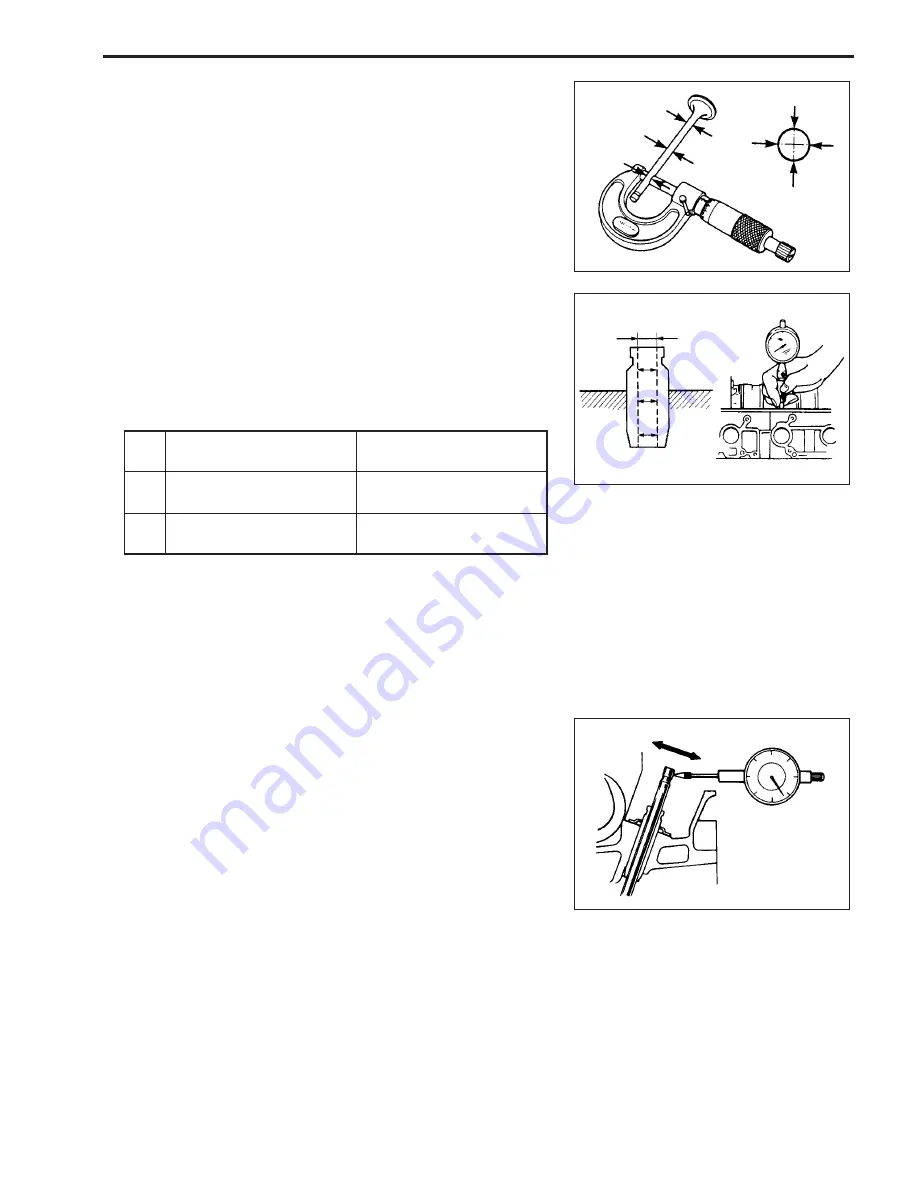
To check the clearance, measure the following items:
• Valve stem outside diameter
• Valve guide inside diameter
$
09900-20205: Micrometer
Small bore gauge or Dial calipers
Standard:
Valve stem
Valve guide
outside diameter
inside diameter
6.965 – 6.980 mm
7.000 – 7.015 mm
(0.2742 – 0.2748 in)
(0.2756 – 0.2762 in)
6.940 – 6.955 mm
7.000 – 7.015 mm
(0.2732 – 0.2738 in)
(0.2756 – 0.2762 in)
IN
EX
If you are unable to measure the valve guide inside diameter,
measure the “Valve stem end deflection”.
Valve stem end deflection
Measure the valve stem end deflection as follows:
1. Install the valve into the valve guide.
2. Position the valve head at approx. 10 mm away from the valve
seat.
3. Move the stem end in the direction “X – Y”, and measure the
deflection.
$
09900-20602: Dial gauge
09900-20701: Magnetic stand
Service limit: IN 0.14 mm (0.006 in)
EX 0.18 mm (0.007 in)
If the measurement exceeds the service limit, replace the valve.
If the measurement still exceeds the service limit with a new
valve, replace the valve guide.
NOTE:
For the valve guide replacement, see the “VALVE GUIDE RE-
PLACEMENT” section on the page 6-23.
X
Y


