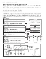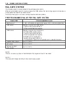
ENGINE CONTROL SYSTEM 3-15
In.
Cm.
Ep.
Ex.
In.
Cm.
Ep.
Ex.
In.
TDC
TDC
TDC
TDC
10˚
120˚
120˚
120˚
4-signals/720˚
34-signals/360˚
Injection time duration
BTDC 484˚ on exhaust stroke
CKP sensor
signal
CMP sensor
signal
#1 Injection
signal
#3 Injection
signal
#4 Injection
signal
In. : Intake, Cm. : Compression, Ep. : Explosion, Ex. : Exhaust, TDC : Top Dead Center
ON
OFF
TDC
TDC
TDC
TDC
TDC
TDC
TDC
TDC
Ep.
Ex.
In.
Cm.
Ep.
Ex.
In.
Cm.
Ep.
TDC
TDC
TDC
TDC
Cm.
Ep.
Ex.
In.
Cm.
Ep.
Ex.
In.
Cm.
#2 Injection
signal
Ex.
In.
Cm.
Ep.
Ex.
In.
Cm.
Ep.
Ex.
30˚
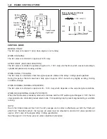
CONTROL MODE
BEFORE START:
When the ignition switch is turned “ON”, the ECM receives a MAP sensor signal, indicating the static baro-
metric pressure of the intake manifold, which is used to compensate the fuel injection map for altitude.
WHEN CRANKING:
Fuel is simultaneously injected to all cylinders every time any piston is positioned at compression stroke.
AFTER START (FAST-IDLE FUNCTION):
The fuel injection amount is controlled to increase until the timer, set according to cylinder temperature at the
time of engine start, expires.
WHEN IDLING/TROLLING:
The fuel injection amount is controlled to maintain a stable engine speed at the specified idle/trolling rpm.
WHEN ACCELERATING:
The fuel injection amount is controlled to increase.
WHEN DECELERATING:
The fuel injection amount is controlled to decrease.
The fuel injection is also cut off on very rapid engine deceleration.
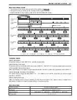
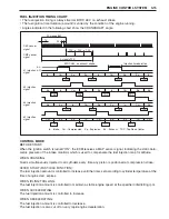
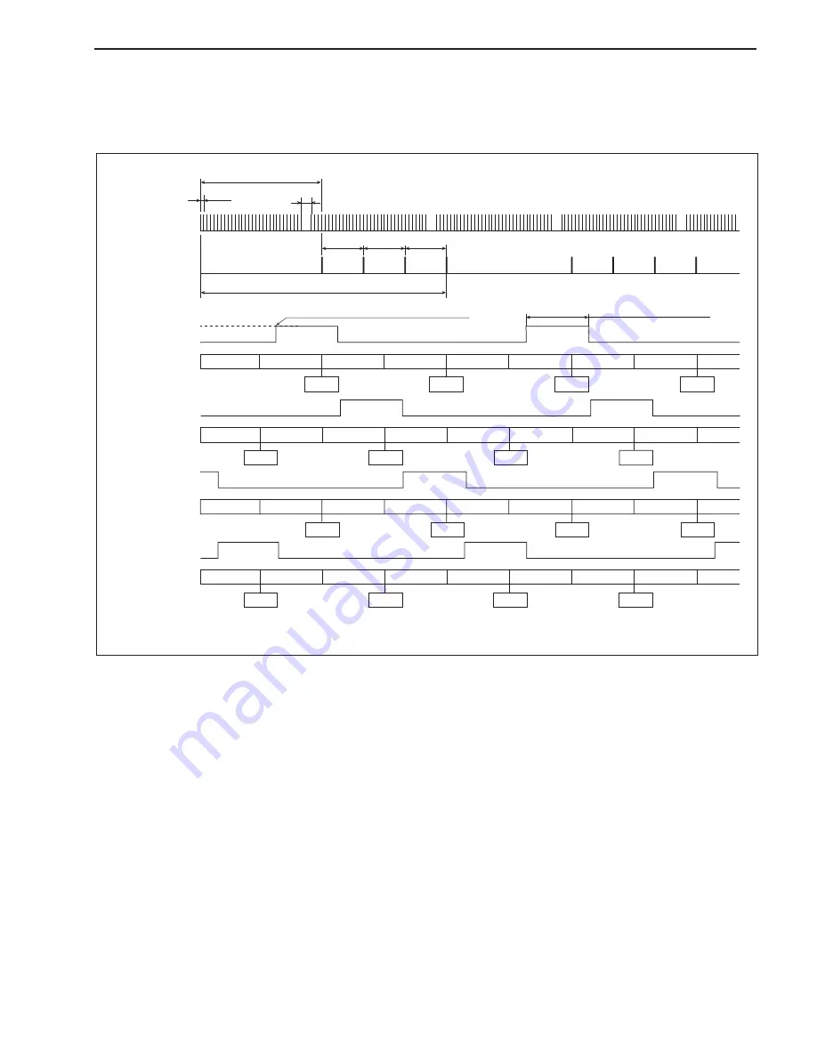
FUEL INJECTION TIMING CHART
• The fuel injection timing is always fixed at BTDC 484° on exhaust stroke.
• The fuel ignition time duration (amount) is varied by the condition of the engine running.
• Angles indicated in the following chart show the CRANKSHAFT angle.

