ENGINE 3-83
REASSEMBLY
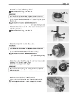
• Press the bearings
1
and
2
with the special tool.
#
%
09913-70210: Bearing installer set
Bearing
1
:
-
52 Attachment
Bearing
2
:
-
47 Attachment
• Install the snap ring
3
.
#
• Install the generator stator
4
, CKP sensor
5
, bracket
6
and
grommet
7
and tighten them to the specified torque.
NOTE:
When installing the generator stator and CUP sensor, route the
wire properly.
"
Generator starter bolt: 11 N·m (1.1 kgf-m, 8.0 lb-ft)
CKP sensor mount bolt: 6 N·m (0.6 kgf-m, 4.3 lb-ft)
Bracket bolt: 6 N·m (0.6 kgf-m, 4.3 lb-ft)
• Install the oil seals
4
and
5
with the special tool.
#
%
09913-70210: Bearing installer set
Oil seal
4
:
-
42 Attachment
Oil seal
5
:
-
20 Attachment
• Apply SUZUKI SUPER GREASE “A” to the lip of the oil seals.
,
09900-25010: SUZUKI SUPER GREASE “A”
(or equivalent grease)
The re moved bearings m ust be rep laced with n ew
ones.
The removed snap ring must be replaced with a new
one.
The r emoved o il s eals m ust be replaced wit h ne w
ones.
Summary of Contents for LT-A450X
Page 2: ...SUPPLEMENTS LT A450XK9 09 MODEL LT A450XK8 12 13 WIRING DIAGRAM 14 ...
Page 47: ...PERIODIC MAINTENANCE 2 29 ...
Page 48: ...2 30 PERIODIC MAINTENANCE ...
Page 63: ...ENGINE 3 7 Remove the engine mounting nuts Remove the engine from the right side ...
Page 215: ......
Page 315: ...7 24 COOLING AND LUBRICATION SYSTEM ENGINE LUBRICATION SYSTEM To cylinder head OIL PUMP ...
Page 316: ...COOLING AND LUBRICATION SYSTEM 7 25 EXHAUST SIDE INTAKE SIDE ...
Page 317: ......
Page 332: ...8 14 CHASSIS REAR CARRIER Remove the rear carrier REAR BOX Remove the rear box 1 ...
Page 417: ......
Page 452: ...9 34 ELECTRICAL SYSTEM HEADLIGHT INSTALLATION Head light coupler Head light R Adjusting point ...
Page 484: ...10 26 SERVICING INFORMATION Rear box Rear fender Right mud guard Left mud guard ...
Page 510: ......
Page 514: ......


