3-98 ENGINE
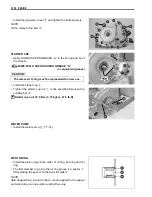
• Install the clutch inner cover gasket and clutch inner cover
2
.
#
• Tighten the clutch inner cover bolts to the specified torque.
#
"
Clutch inner cover bolt: 9 N·m (0.9 kgf-m, 6.5 lb-ft)
FIXED DRIVE FACE
• Install the fixed drive face
1
.
#
MOVABLE DRIVEN FACE AND DRIVE BELT
• Install the drive belt, as low as possible, between the movable
driven face and fixed driven face by tapping with a plastic mal-
let.
#
• Install the movable driven face assembly
1
.
#
The r emoved cl utch in ner cov er ga sket must b e
replaced with a new one.
Tighten the clutch inner cover bolts
A
first and then
other ones diagonally.
Degrease th e fi xed d rive f ace. Use no nflammable
cleaning solvent to wipe off oily or greasy matter and
make its surfaces completely dry.
* The drive belt should be installed so that the arrows
on the drive belt periphery point in the normal turn-
ing direction.
* The dr ive b elt co ntact surface of t he d riven f ace
should be thoroughly cleaned.
Pull the center area
A
of upper and lower belt lines to
be close to eac h o ther to pr event the b elt f rom
expanding.
Summary of Contents for LT-A450X
Page 2: ...SUPPLEMENTS LT A450XK9 09 MODEL LT A450XK8 12 13 WIRING DIAGRAM 14 ...
Page 47: ...PERIODIC MAINTENANCE 2 29 ...
Page 48: ...2 30 PERIODIC MAINTENANCE ...
Page 63: ...ENGINE 3 7 Remove the engine mounting nuts Remove the engine from the right side ...
Page 215: ......
Page 315: ...7 24 COOLING AND LUBRICATION SYSTEM ENGINE LUBRICATION SYSTEM To cylinder head OIL PUMP ...
Page 316: ...COOLING AND LUBRICATION SYSTEM 7 25 EXHAUST SIDE INTAKE SIDE ...
Page 317: ......
Page 332: ...8 14 CHASSIS REAR CARRIER Remove the rear carrier REAR BOX Remove the rear box 1 ...
Page 417: ......
Page 452: ...9 34 ELECTRICAL SYSTEM HEADLIGHT INSTALLATION Head light coupler Head light R Adjusting point ...
Page 484: ...10 26 SERVICING INFORMATION Rear box Rear fender Right mud guard Left mud guard ...
Page 510: ......
Page 514: ......


