FI SYSTEM DIAGNOSIS 5-15
SELF-DIAGNOSIS FUNCTION
The self-diagnosis function is incorporated in the ECM. The function has two modes, “User mode” and
“Dealer mode”. The user can only be notified by the LCD (FI) panel and LED (FI light). To check the function
of the individual FI system devices, the dealer mode is prepared. In this check, the special tool is necessary
to read the code of the malfunction items.
USER MODE
*1
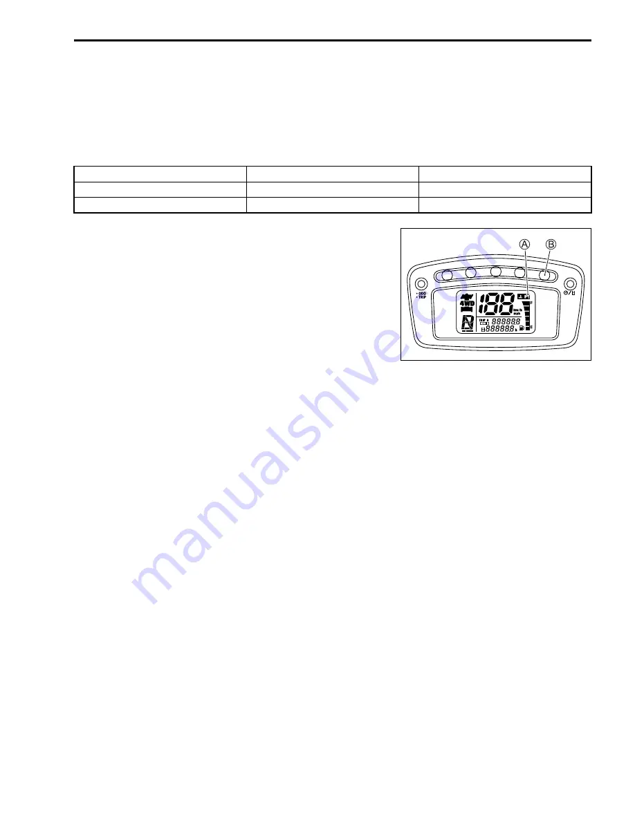
When one of the signals is not received by ECM, the fail-safe
circuit works and injection is not stopped. In this case, “FI” is
indicated in the LCD panel and vehicle can run.
*2
The injection signal is stopped, when the crankshaft position
sensor signal, tip-over sensor signal, ignition signal, injector sig-
nal, fuel pump relay signal or ignition switch signal is not sent to
ECM. In this case, “FI” is indicated in the LCD panel. Vehicle
does not run.
“CHEC”: The LCD panel indicates “CHEC” when no communication signal from the ECM is received for 3
seconds.
For Example
: The ignition switch is turned ON, and the engine stop switch is turned OFF. In this case, the com-
bination meter does not receive any signal from ECM, and the panel indicates “CHEC”.
If CHEC is indicated, the LCD does not indicate the trouble code. It is necessary to check the wir-
ing harness between ECM and combination meter couplers.
The possible cause of this indication is as follows;
Engine stop switch is in OFF position. Ignition fuse is burnt.
NOTE:
Until starting the engine, the FI light turns ON.
The FI light is also turned ON when engine temperature is high.
MALFUNCTION
LCD (FI)
A
INDICATION
FI LIGHT
B
INDICATION
Engine can start
“FI” letter. *1
FI light turns ON.
Engine can not start
“FI” letter indicates and flickers. *2
FI light turns ON and blinks.
Summary of Contents for LT-A450X
Page 2: ...SUPPLEMENTS LT A450XK9 09 MODEL LT A450XK8 12 13 WIRING DIAGRAM 14 ...
Page 47: ...PERIODIC MAINTENANCE 2 29 ...
Page 48: ...2 30 PERIODIC MAINTENANCE ...
Page 63: ...ENGINE 3 7 Remove the engine mounting nuts Remove the engine from the right side ...
Page 215: ......
Page 315: ...7 24 COOLING AND LUBRICATION SYSTEM ENGINE LUBRICATION SYSTEM To cylinder head OIL PUMP ...
Page 316: ...COOLING AND LUBRICATION SYSTEM 7 25 EXHAUST SIDE INTAKE SIDE ...
Page 317: ......
Page 332: ...8 14 CHASSIS REAR CARRIER Remove the rear carrier REAR BOX Remove the rear box 1 ...
Page 417: ......
Page 452: ...9 34 ELECTRICAL SYSTEM HEADLIGHT INSTALLATION Head light coupler Head light R Adjusting point ...
Page 484: ...10 26 SERVICING INFORMATION Rear box Rear fender Right mud guard Left mud guard ...
Page 510: ......
Page 514: ......


