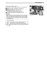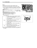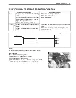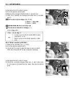
FI SYSTEM DIAGNOSIS 5-25
MALFUNCTION CODE AND DEFECTIVE CONDITION
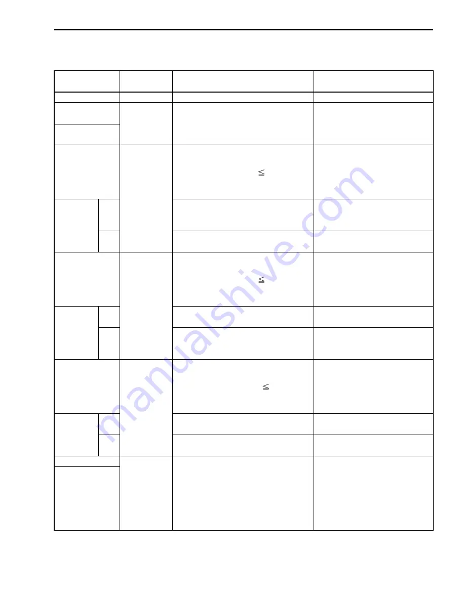
DTC No.
DETECTED
ITEM
DETECTED FAILURE CONDITION
CHECK FOR
C00
NO FAULT
–––––––––––
–––––––––––
C12
CKP sensor
The signal does not reach ECM for 3
sec. or more, after receiving the starter
signal.
CKP sensor lead wire/coupler
and mechanical parts.
CKP sensor, lead wire/coupler
connection
P0335
C13
IAP sensor
The sensor should produce following
voltage.
0.5 V < sensor voltage
4.85 V
In other than the above value, C13
(P0105) is indicated.
IAP sensor, lead wire/coupler
connection.
P0105
H
Sensor voltage is higher than specified
value.
IAP sensor circuit open or
shorted to VCC or ground circuit
open.
L
Sensor voltage is lower than specified
value.
IAP sensor circuit shorted to
ground or VCC circuit open.
C14
TP sensor
The sensor should produce following
voltage.
0.2 V < sensor voltage
4.8 V
In other than the above value, C14
(P0120) is indicated.
TP sensor, lead wire/coupler
connection.
P0120
H
Sensor voltage is higher than specified
value.
TP sensor circuit shorted to
VCC or ground circuit open.
L
Sensor voltage is lower than specified
value.
TP sensor circuit open or
shorted to ground or VCC circuit
open.
C15
ECT sensor
The sensor voltage should be the fol-
lowing.
0.15 V < sensor voltage
4.85 V
In other than the above value, C15
(P0115) is indicated.
ECT sensor, lead wire/coupler
connection.
P0115
H
Sensor voltage is higher than specified
value.
ECT sensor circuit open or
ground circuit open.
L
Sensor voltage is lower than specified
value.
ECT sensor circuit shorted to
ground.
C20
Diff-lock relay No voltage is applied to 4WD/diff-lock
actuator, although ignition switch is
turned ON, or voltage is applied to
4WD/diff-lock actuator, although igni-
tion switch is turned OFF.
In this case, the code C20 (P1752) is
indicated.
Diff-lock relay circuit open or
shorted to ground.
P1752
Summary of Contents for LT-A450X
Page 2: ...SUPPLEMENTS LT A450XK9 09 MODEL LT A450XK8 12 13 WIRING DIAGRAM 14 ...
Page 47: ...PERIODIC MAINTENANCE 2 29 ...
Page 48: ...2 30 PERIODIC MAINTENANCE ...
Page 63: ...ENGINE 3 7 Remove the engine mounting nuts Remove the engine from the right side ...
Page 215: ......
Page 315: ...7 24 COOLING AND LUBRICATION SYSTEM ENGINE LUBRICATION SYSTEM To cylinder head OIL PUMP ...
Page 316: ...COOLING AND LUBRICATION SYSTEM 7 25 EXHAUST SIDE INTAKE SIDE ...
Page 317: ......
Page 332: ...8 14 CHASSIS REAR CARRIER Remove the rear carrier REAR BOX Remove the rear box 1 ...
Page 417: ......
Page 452: ...9 34 ELECTRICAL SYSTEM HEADLIGHT INSTALLATION Head light coupler Head light R Adjusting point ...
Page 484: ...10 26 SERVICING INFORMATION Rear box Rear fender Right mud guard Left mud guard ...
Page 510: ......
Page 514: ......


