COOLING AND LUBRICATION SYSTEM 7-19
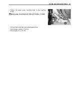
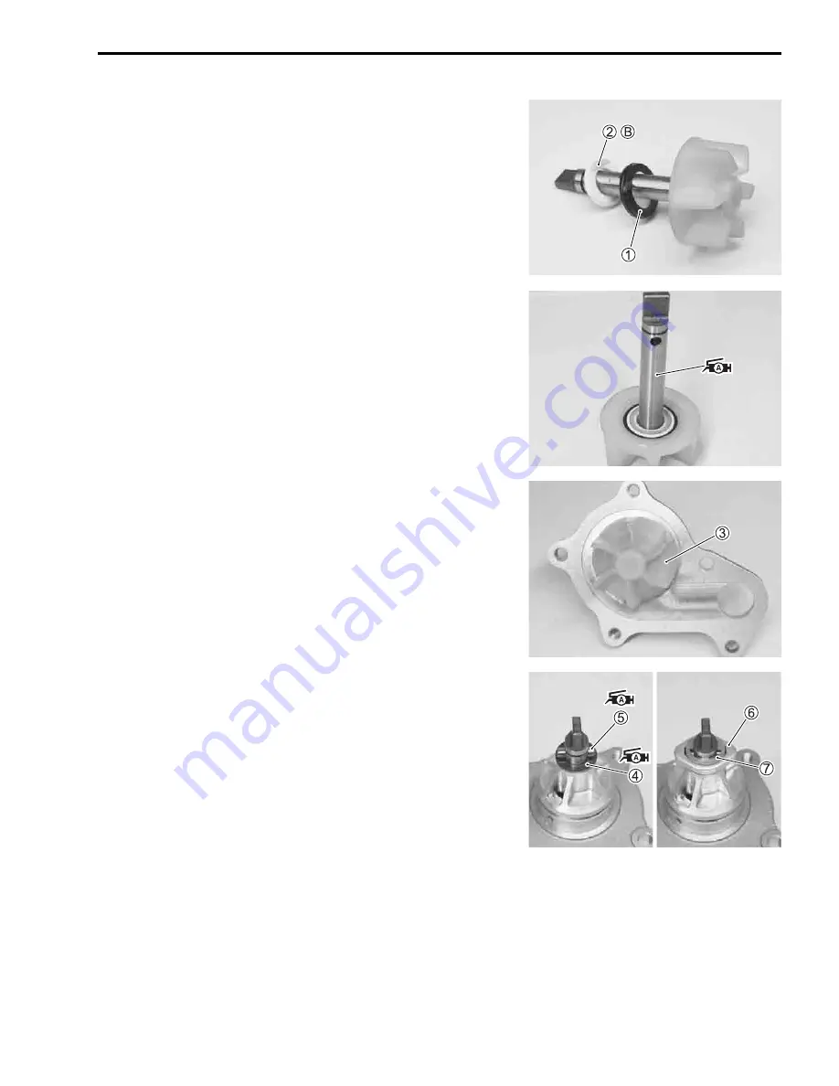
• Install the rubber seal
1
into the impeller.
• After wiping off the oily or greasy matter from the mechanical
seal ring
2
, install it into the impeller.
NOTE:
The paint marked side
B
of the mechanical seal ring faces the
impeller.
• Apply SUZUKI SUPER GREASE “A” to the impeller shaft.
,
99000-25010: SUZUKI SUPER GREASE “A”
(or equivalent grease)
• Install the impeller shaft
3
to the water pump body.
• Apply SUZUKI SUPER GREASE “A” to the washer and pin
holder.
,
99000-25010: SUZUKI SUPER GREASE “A”
(or equivalent grease)
• Install the washer
4
, pin
5
, pin holder
6
and E-ring
7
.
Summary of Contents for LT-A450X
Page 2: ...SUPPLEMENTS LT A450XK9 09 MODEL LT A450XK8 12 13 WIRING DIAGRAM 14 ...
Page 47: ...PERIODIC MAINTENANCE 2 29 ...
Page 48: ...2 30 PERIODIC MAINTENANCE ...
Page 63: ...ENGINE 3 7 Remove the engine mounting nuts Remove the engine from the right side ...
Page 215: ......
Page 315: ...7 24 COOLING AND LUBRICATION SYSTEM ENGINE LUBRICATION SYSTEM To cylinder head OIL PUMP ...
Page 316: ...COOLING AND LUBRICATION SYSTEM 7 25 EXHAUST SIDE INTAKE SIDE ...
Page 317: ......
Page 332: ...8 14 CHASSIS REAR CARRIER Remove the rear carrier REAR BOX Remove the rear box 1 ...
Page 417: ......
Page 452: ...9 34 ELECTRICAL SYSTEM HEADLIGHT INSTALLATION Head light coupler Head light R Adjusting point ...
Page 484: ...10 26 SERVICING INFORMATION Rear box Rear fender Right mud guard Left mud guard ...
Page 510: ......
Page 514: ......


