CHASSIS 8-35
BRAKE DISC INSPECTION
• Remove the front wheel. (
$
8-18)
• Remove the brake caliper. (
$
8-29)
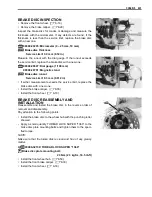
Inspect the brake disc for cracks or damage and measure the
thickness with the micrometer. If any defects are found, if the
thickness is less than the service limit, replace the brake disc
with a new one.
%
09900-20205: Micrometer (0 – 25 mm, 10 mm)
&
Brake disc thickness
Service Limit: 3.0 mm (0.12 in)
Measure the runout with the dial gauge. If the runout exceeds
the service limit, replace the brake disc with a new one.
%
09900-20607: Dial gauge (1/100 mm)
09900-20701: Magnetic stand
&
Brake disc runout
Service Limit: 0.3 mm (0.012 in)
• If either measurement exceeds the service limit, replace the
brake disc with a new one.
• Install the brake caliper. (
$
8-33)
• Install the front wheel. (
$
8-18)
BRAKE DISC REASSEMBLY AND
INSTALLATION
Reassemble and install the brake disc in the reverse order of
removal and disassembly.
Pay attention to the following points:
• Install the brake disc to the wheel hub with the punching letter
showed.
• Apply a small quantity THREAD LOCK SUPER “1360” to the
brake disc plate mounting bolts and tighten them to the speci-
fied torque.
NOTE:
Make sure that the brake disk is clean and free of any greasy
matter.
9
99000-32130: THREAD LOCK SUPER “1360”
"
Brake disc plate mounting bolt:
23 N·m (2.3 kgf·m, 16.5 lb-ft)
• Install the front wheel hub. (
$
8-50)
• Install the front brake caliper. (
$
8-33)
• Install the front wheel. (
$
8-18)
Summary of Contents for LT-A450X
Page 2: ...SUPPLEMENTS LT A450XK9 09 MODEL LT A450XK8 12 13 WIRING DIAGRAM 14 ...
Page 47: ...PERIODIC MAINTENANCE 2 29 ...
Page 48: ...2 30 PERIODIC MAINTENANCE ...
Page 63: ...ENGINE 3 7 Remove the engine mounting nuts Remove the engine from the right side ...
Page 215: ......
Page 315: ...7 24 COOLING AND LUBRICATION SYSTEM ENGINE LUBRICATION SYSTEM To cylinder head OIL PUMP ...
Page 316: ...COOLING AND LUBRICATION SYSTEM 7 25 EXHAUST SIDE INTAKE SIDE ...
Page 317: ......
Page 332: ...8 14 CHASSIS REAR CARRIER Remove the rear carrier REAR BOX Remove the rear box 1 ...
Page 417: ......
Page 452: ...9 34 ELECTRICAL SYSTEM HEADLIGHT INSTALLATION Head light coupler Head light R Adjusting point ...
Page 484: ...10 26 SERVICING INFORMATION Rear box Rear fender Right mud guard Left mud guard ...
Page 510: ......
Page 514: ......

