PERIODIC MAINTENANCE 2-25
AIR BLEEDING THE BRAKE FLUID CIRCUIT
Air trapped in the brake fluid circuit acts like a cushion absorb a
large proportion of the pressure developed by the master cylin-
der and thus interferes with the full braking performance of the
brake caliper. The presence of air is indicated by “sponginess”
of the brake lever and also by lack of braking force. Considering
the danger to which such trapped air exposes the machine and
rider, it is essential that, after installing the brake and restoring
the brake system to the normal condition, the brake fluid circuit
be purged of air in the following manner:
• Fill the front or rear brake reservoir with the specified brake
fluid to the top of the inspection window or the upper limit line.
Replace the reservoir cap to prevent dirt from entering.
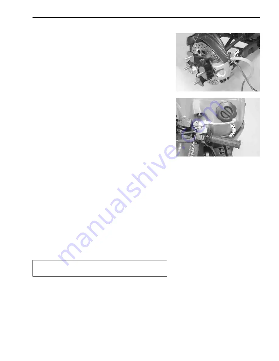
• Attach a hose to the air bleeder valve, and insert the free end
of the hose into a receptacle.
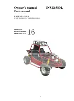
• Squeeze and release the brake lever several times in rapid
succession and squeeze the lever fully without releasing it.
Loosen the air bleeder valve by turning it a quarter of a turn so
that the brake fluid runs into the receptacle, this will remove
the tension of the brake lever causing it to touch the handle-
bar grip reaching bottom of the stroke. Then, close the air
bleeder valve, pump and squeeze the lever and open the
valve. Repeat this process until the fluid flowing into the
receptacle no longer contains air bubbles.
NOTE:
While bleeding the brake system, replenish the brake fluid in the
reservoir as necessary. Make sure that there is always some
fluid visible in the reservoir.
• Close the air bleeder valve, and disconnect the hose. Fill the
reservoir with brake fluid to the top of the inspection window
or the upper limit line.
"
Front brake air bleeder valve:
6.0 N·m (0.6 kgf-m, 4.3 lb-ft)
#
Handle brake fl uid with ca re: th e f luid r eacts ch emi-
cally with paint, plastics, rubber materials, etc.
Summary of Contents for LT-A450X
Page 2: ...SUPPLEMENTS LT A450XK9 09 MODEL LT A450XK8 12 13 WIRING DIAGRAM 14 ...
Page 47: ...PERIODIC MAINTENANCE 2 29 ...
Page 48: ...2 30 PERIODIC MAINTENANCE ...
Page 63: ...ENGINE 3 7 Remove the engine mounting nuts Remove the engine from the right side ...
Page 215: ......
Page 315: ...7 24 COOLING AND LUBRICATION SYSTEM ENGINE LUBRICATION SYSTEM To cylinder head OIL PUMP ...
Page 316: ...COOLING AND LUBRICATION SYSTEM 7 25 EXHAUST SIDE INTAKE SIDE ...
Page 317: ......
Page 332: ...8 14 CHASSIS REAR CARRIER Remove the rear carrier REAR BOX Remove the rear box 1 ...
Page 417: ......
Page 452: ...9 34 ELECTRICAL SYSTEM HEADLIGHT INSTALLATION Head light coupler Head light R Adjusting point ...
Page 484: ...10 26 SERVICING INFORMATION Rear box Rear fender Right mud guard Left mud guard ...
Page 510: ......
Page 514: ......


