9-30 ELECTRICAL SYSTEM
INSPECTION
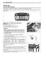
LED (LIGHT EMITTING DIODE)
Check that the LED lights (diff-lock, reverse, neutral and ECT/FI) immediately after turning the ignition
switch ON. Also, check them for lighting in accordance with their switch positions.
If the LED fails in operation, replace the combination meter unit with a new one after checking its wire har-
ness/coupler.
ENGINE COOLANT TEMPERATURE METER AND
INDICATOR
ECT sensor inspection. (
$
7-11)
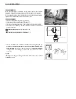
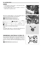
• Remove the right side cover. (
$
8-10)
• Disconnect the ECT sensor coupler
1
.
#
• Connect the variable resistor
A
between the terminals.
• Turn the ignition switch ON.
• Check the LCD and LED operations when the resistance is
adjusted to the specified values.
If either one or all indications are abnormal, replace the combi-
nation meter with a new one.
NOTE:
If the engine stop switch is turned OFF while the ignition switch
is ON, the LCD displays “CHEC”. But it is not a malfunction.
This condition implies that combination meter receives no signal
from the ECM.
In that case, they are restored to normal indication by turning the
engine stop switch to “
A
” (RUN) position.
When connecting and disconnecting the engine cool-
ant temperature sensor lead wire coupler, make sure
to turn OFF the ign ition sw itch, or el ectronic parts
may get damaged.
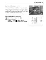
Resistance
A
LED
B
LCD
C
Water temperature
Approx. 0.14 k
Ω
OFF
OFF
Approx. 110 °C
0
Ω
(Jumper wire)
ON
ON
120 °C and over
Summary of Contents for LT-A450X
Page 2: ...SUPPLEMENTS LT A450XK9 09 MODEL LT A450XK8 12 13 WIRING DIAGRAM 14 ...
Page 47: ...PERIODIC MAINTENANCE 2 29 ...
Page 48: ...2 30 PERIODIC MAINTENANCE ...
Page 63: ...ENGINE 3 7 Remove the engine mounting nuts Remove the engine from the right side ...
Page 215: ......
Page 315: ...7 24 COOLING AND LUBRICATION SYSTEM ENGINE LUBRICATION SYSTEM To cylinder head OIL PUMP ...
Page 316: ...COOLING AND LUBRICATION SYSTEM 7 25 EXHAUST SIDE INTAKE SIDE ...
Page 317: ......
Page 332: ...8 14 CHASSIS REAR CARRIER Remove the rear carrier REAR BOX Remove the rear box 1 ...
Page 417: ......
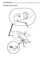
Page 452: ...9 34 ELECTRICAL SYSTEM HEADLIGHT INSTALLATION Head light coupler Head light R Adjusting point ...
Page 484: ...10 26 SERVICING INFORMATION Rear box Rear fender Right mud guard Left mud guard ...
Page 510: ......
Page 514: ......


