9-40 ELECTRICAL SYSTEM
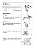
Measure the battery voltage using multi circuit tester. The tester
should indicate more than 12.5 – 12.6 V (DC) as shown in the
Fig. If the battery voltage is lower than the specification, charge
the battery with a battery charger. (Refer to the recharging oper-
ation)
#
NOTE:
Initial charging for a new battery is recommended if two years
have elapsed since the date of manufacture.
SERVICING
Visually inspect the surface of the battery container. If any signs
of cracking or electrolyte leakage from the sides of the battery
have occurred, replace the battery with a new one. If the battery
terminals are found to be coated with rust or an acidic white
powdery substance, clean the battery terminals with sandpaper.
RECHARGING OPERATION
• Using the multi-circuit tester, check the battery voltage. If the
voltage reading is 12.0 V (DC) and less, recharge the battery
with a battery charger.
A
Charging period
B
Stop charging
#
Recharging time: 6 A for 1 hour or 1.2 A for 5 to 10 hours
#
• After recharging, wait for 30 minutes and more and check the
battery voltage with a multi-circuit tester.
• If the battery voltage is 12.5 V and less, recharge the battery
again.
• If battery voltage is still 12.5 V and less, after recharging,
replace the battery with a new one.
• When the vehicle is not used for a long period (especially dur-
ing the winter season), check the battery every 1 month to
prevent the battery discharge.
Do no t re move t he ca ps o n th e b attery to p wh ile
charging.
13
12
11
10
0
2
4
6
8
10
(V)
30 second
(at 25 ˚C)
Time
(Minutes)
* When r echarging th e b attery, r emove the bat tery
from the vehicle.
* Do not remove the ca ps on the ba ttery top while
recharging.
Be c areful no t to p ermit the ch arging c urrent to
exceed 9 A at any time.
(V)
(at 0 ˚– 40 ˚C)
14
13
12
11
10
100
Battety charged condition
75
50
25
0 (%)
Summary of Contents for LT-A450X
Page 2: ...SUPPLEMENTS LT A450XK9 09 MODEL LT A450XK8 12 13 WIRING DIAGRAM 14 ...
Page 47: ...PERIODIC MAINTENANCE 2 29 ...
Page 48: ...2 30 PERIODIC MAINTENANCE ...
Page 63: ...ENGINE 3 7 Remove the engine mounting nuts Remove the engine from the right side ...
Page 215: ......
Page 315: ...7 24 COOLING AND LUBRICATION SYSTEM ENGINE LUBRICATION SYSTEM To cylinder head OIL PUMP ...
Page 316: ...COOLING AND LUBRICATION SYSTEM 7 25 EXHAUST SIDE INTAKE SIDE ...
Page 317: ......
Page 332: ...8 14 CHASSIS REAR CARRIER Remove the rear carrier REAR BOX Remove the rear box 1 ...
Page 417: ......
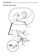
Page 452: ...9 34 ELECTRICAL SYSTEM HEADLIGHT INSTALLATION Head light coupler Head light R Adjusting point ...
Page 484: ...10 26 SERVICING INFORMATION Rear box Rear fender Right mud guard Left mud guard ...
Page 510: ......
Page 514: ......


