10-2 SERVICING INFORMATION
TROUBLESHOOTING
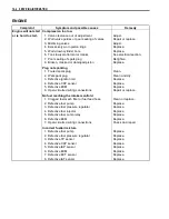
FI SYSTEM MALFUNCTION CODE AND DEFECTIVE CONDITION
DTC No.
DETECTED
ITEM
DETECTED FAILURE CONDITION
CHECK FOR
C00
NO FAULT
–––––––––––
–––––––––––
C12
CKP sensor
The signal does not reach ECM for 3
sec. or more, after receiving the starter
signal.
CKP sensor lead wire/coupler
and mechanical parts.
CKP sensor, lead wire/coupler
connection
P0335
C13
IAP sensor
The sensor should produce following
voltage.
0.5 V < sensor voltage
4.85 V
In other than the above value, C13
(P0105) is indicated.
IAP sensor, lead wire/coupler
connection.
P0105
H
Sensor voltage is higher than specified
value.
IAP sensor circuit open or
shorted to VCC or ground circuit
open.
L
Sensor voltage is lower than specified
value.
IAP sensor circuit shorted to
ground or VCC circuit open.
C14
TP sensor
The sensor should produce following
voltage.
0.2 V < sensor voltage
4.8 V
In other than the above value, C14
(P0120) is indicated.
TP sensor, lead wire/coupler
connection.
P0120
H
Sensor voltage is higher than specified
value.
TP sensor circuit shorted to
VCC or ground circuit open.
L
Sensor voltage is lower than specified
value.
TP sensor circuit open or
shorted to ground or VCC circuit
open.
C15
ECT sensor
The sensor voltage should be the fol-
lowing.
0.15 V < sensor voltage
4.85 V
In other than the above value, C15
(P0115) is indicated.
ECT sensor, lead wire/coupler
connection.
P0115
H
Sensor voltage is higher than specified
value.
ECT sensor circuit open or
ground circuit open.
L
Sensor voltage is lower than specified
value.
ECT sensor circuit shorted to
ground.
C20
Diff-lock relay No voltage is applied to 4WD/diff-lock
actuator, although ignition switch is
turned ON, or voltage is applied to
4WD/diff-lock actuator, although igni-
tion switch is turned OFF.
In this case, the code C20 (P1752) is
indicated.
Diff-lock relay circuit open or
shorted to ground.
P1752
Summary of Contents for LT-A450X
Page 2: ...SUPPLEMENTS LT A450XK9 09 MODEL LT A450XK8 12 13 WIRING DIAGRAM 14 ...
Page 47: ...PERIODIC MAINTENANCE 2 29 ...
Page 48: ...2 30 PERIODIC MAINTENANCE ...
Page 63: ...ENGINE 3 7 Remove the engine mounting nuts Remove the engine from the right side ...
Page 215: ......
Page 315: ...7 24 COOLING AND LUBRICATION SYSTEM ENGINE LUBRICATION SYSTEM To cylinder head OIL PUMP ...
Page 316: ...COOLING AND LUBRICATION SYSTEM 7 25 EXHAUST SIDE INTAKE SIDE ...
Page 317: ......
Page 332: ...8 14 CHASSIS REAR CARRIER Remove the rear carrier REAR BOX Remove the rear box 1 ...
Page 417: ......
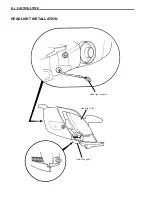
Page 452: ...9 34 ELECTRICAL SYSTEM HEADLIGHT INSTALLATION Head light coupler Head light R Adjusting point ...
Page 484: ...10 26 SERVICING INFORMATION Rear box Rear fender Right mud guard Left mud guard ...
Page 510: ......
Page 514: ......


