3-60 ENGINE
#
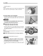
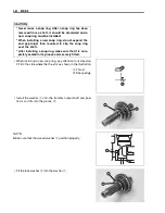
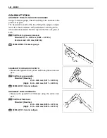
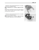
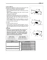
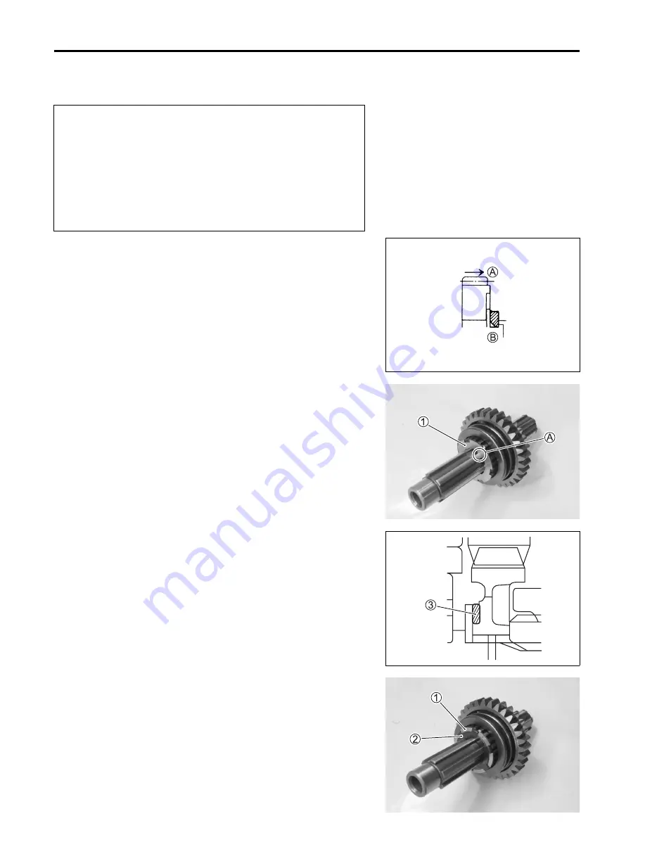
• When installing a new snap ring, pay attention to its directon.
Fit it to the side where the thrust is as shown in the illustration.
A
Thrust
B
Sharp edge
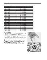
• Install the washer
1
onto the transfer output shaft and posi-
tion it so it fits into the groove
A
.
NOTE:
Make sure that the waved washer
3
position properly.
• Fit the lock washer
2
into the washer
1
.
* Never reuse a snap ring. After a snap ring has been
removed from a shaft, it should be discarded and a
new snap ring must be installed.
* When installing a new snap ring, do not expand the
end gap larger than required to slip the snap ring
over the shaft.
* After installing a snap ring, make sure that it is com-
pletely seated in its groove and securely fitted.
Summary of Contents for LT-A700X 2004
Page 25: ...2 8 PERIODIC MAINTENANCE INTAKE SIDE ...
Page 26: ...PERIODIC MAINTENANCE 2 9 EXHAUST SIDE ...
Page 46: ...PERIODIC MAINTENANCE 2 29 ...
Page 59: ...3 8 ENGINE Remove the engine from the right side ...
Page 133: ...3 82 ENGINE Pull the rope and check that the ratchet is pushed out ...
Page 155: ......
Page 263: ......
Page 301: ...7 20 COOLING AND LUBRICATION SYSTEM EXHAUST SIDE INTAKE SIDE ...
Page 302: ......
Page 312: ...CHASSIS 8 9 REAR CARRIER Remove the rear carrier 1 ...
Page 386: ......
Page 420: ...ELECTRICAL SYSTEM 9 33 HEADLIGHT INSTALLATION Head light coupler Head light R Adjusting point ...
Page 453: ...10 26 SERVICING INFORMATION Rear box Rear fender Right mud guard Left mud guard ...
Page 477: ......
Page 480: ...Prepared by September 2004 Part No 99500 46060 01E Printed in U S A 472 ...

