3-98 ENGINE
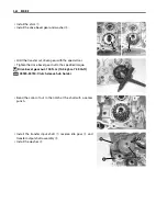
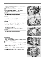
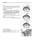
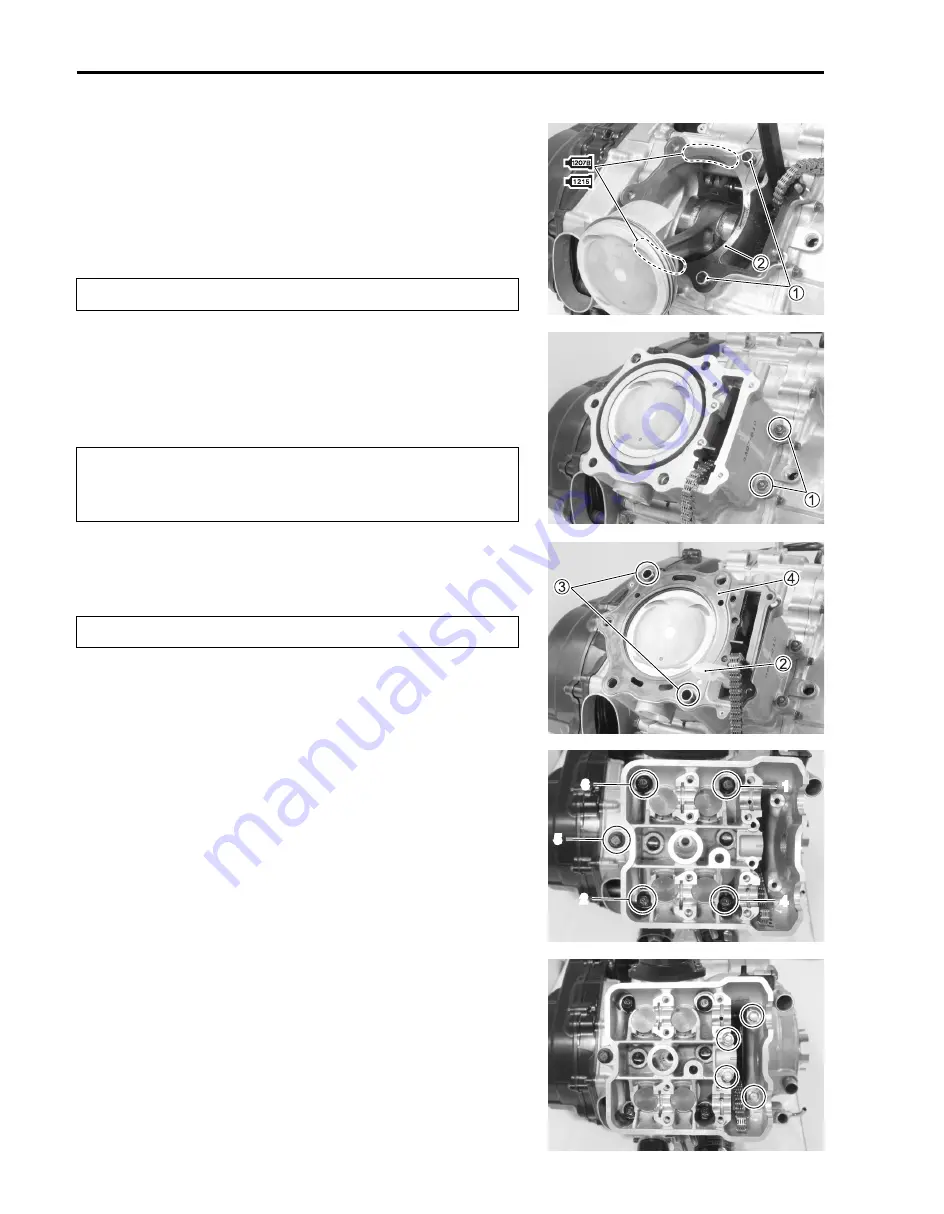
• Coat SUZUKI BOND lightly to the mating surfaces among the
crankcase mating surfaces.
'
99104-31140: SUZUKI BOND “1207B” (USA)
1
99000-31110: SUZUKI BOND “1215” (Others)
• Fit the dowel pins
1
and the new gasket
2
.
#
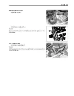
CYLINDER
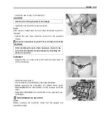
• Hold each piston ring with properly position, insert the piston
into the cylinder.
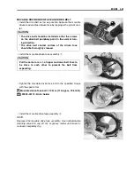
• Tighten the cylinder base nuts
1
.
#
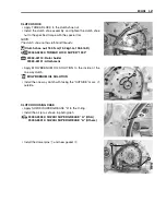
• Install the cam chain guide
2
.
• Fit the dowel pins
3
and new cylinder head gasket
4
.
#
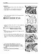
CYLINDER HEAD
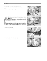
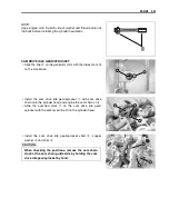
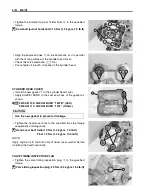
• Install the cylinder head.
• Tighten the cylinder head bolts (M10) in ascending order of
numbers to the specified torque.
"
Cylinder head bolt (M10):
Initial 25 N·m (2.5 kgf-m, 18.0 lb-ft)
Final 37 N·m (3.7 kgf-m, 27.0 lb-ft)
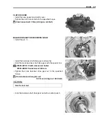
• Tighten the cylinder base nuts
1
.
• Tighten the cylinder head bolts (M6) to the specified torque.
"
Cylinder head bolt (M6) 10 N·m (1.0 kgf-m, 7.0 lb-ft)
Use a new gasket to prevent gas leakage.
When installing the cylinder and cylinder head, pull
the cam chain upward, or the chain will be caught
between the crankcase and cam drive sprocket.
Use a new gasket to prevent gas leakage.
1
4
2
5
3
Summary of Contents for LT-A700X 2004
Page 25: ...2 8 PERIODIC MAINTENANCE INTAKE SIDE ...
Page 26: ...PERIODIC MAINTENANCE 2 9 EXHAUST SIDE ...
Page 46: ...PERIODIC MAINTENANCE 2 29 ...
Page 59: ...3 8 ENGINE Remove the engine from the right side ...
Page 133: ...3 82 ENGINE Pull the rope and check that the ratchet is pushed out ...
Page 155: ......
Page 263: ......
Page 301: ...7 20 COOLING AND LUBRICATION SYSTEM EXHAUST SIDE INTAKE SIDE ...
Page 302: ......
Page 312: ...CHASSIS 8 9 REAR CARRIER Remove the rear carrier 1 ...
Page 386: ......
Page 420: ...ELECTRICAL SYSTEM 9 33 HEADLIGHT INSTALLATION Head light coupler Head light R Adjusting point ...
Page 453: ...10 26 SERVICING INFORMATION Rear box Rear fender Right mud guard Left mud guard ...
Page 477: ......
Page 480: ...Prepared by September 2004 Part No 99500 46060 01E Printed in U S A 472 ...

