ENGINE 3-99
NOTE:
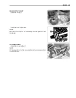
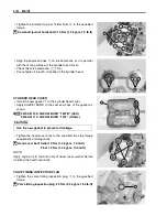
Apply engine oil to the both side of washer and thread portion of
the bolts before installimg the cylinder head bolts.
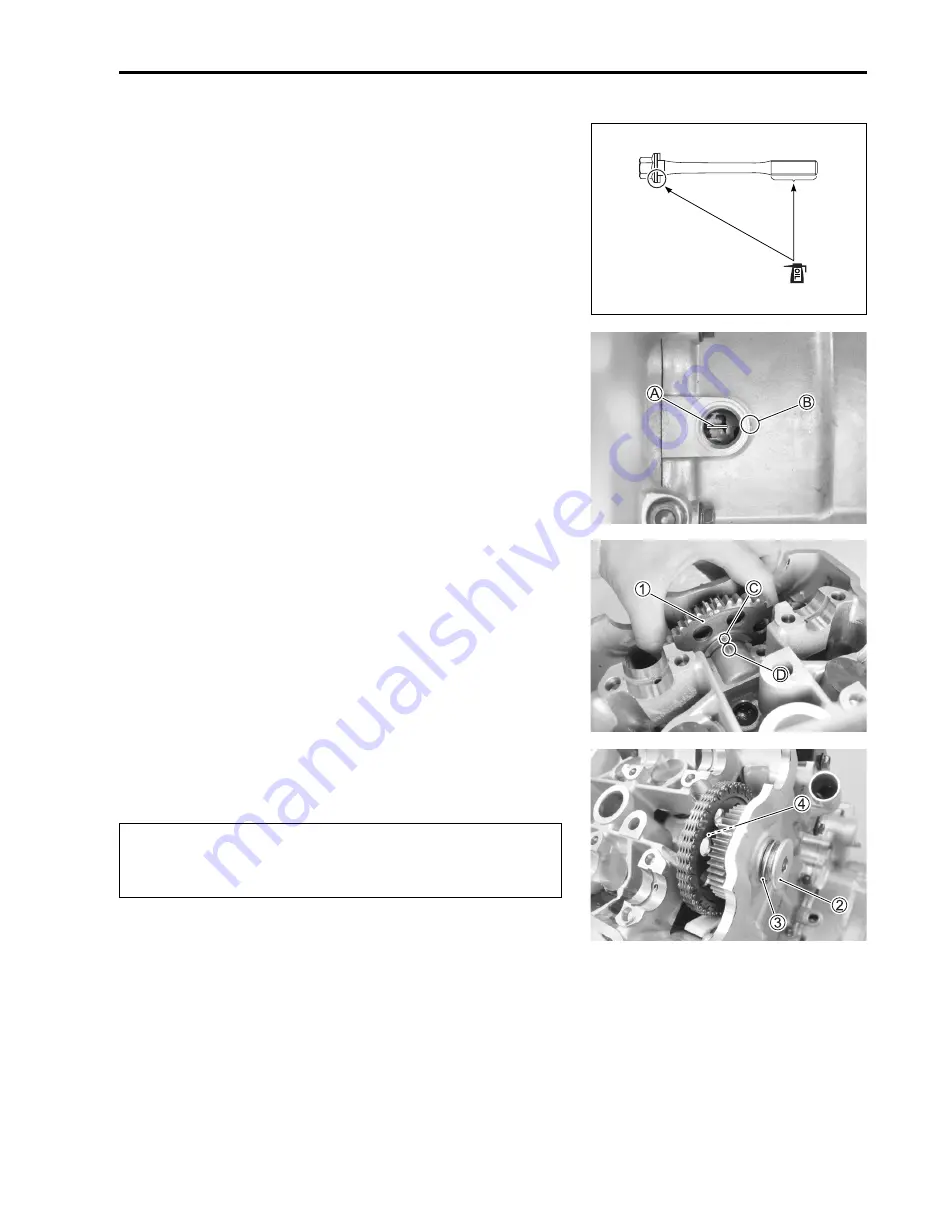
CAM DRIVE IDLE GEAR/SPROCKET
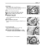
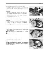
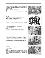
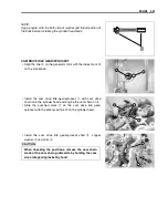
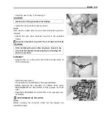
• Align the line
A
on the generator rotor with the index mark
B
on the crankcase.
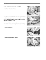
• Install the cam drive idle gear/sprocket
1
with cam drive
chain onto the cylinder head and engine the cam chain on it.
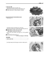
• Aline the punched mark
C
on the cam drive idle gear/
sprocket with the embossed line
D
on the cylinder head.
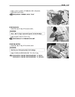
• Install the cam drive idle gear/sprocket shaft
2
, copper
washer
3
and shim
4
.
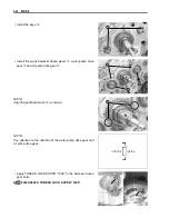
#
When checking the positions, remove the cam chain
slack at the cam chain guide side by holding the cam
drive idle gear/sprocket by hand.
Summary of Contents for LT-A700X 2004
Page 25: ...2 8 PERIODIC MAINTENANCE INTAKE SIDE ...
Page 26: ...PERIODIC MAINTENANCE 2 9 EXHAUST SIDE ...
Page 46: ...PERIODIC MAINTENANCE 2 29 ...
Page 59: ...3 8 ENGINE Remove the engine from the right side ...
Page 133: ...3 82 ENGINE Pull the rope and check that the ratchet is pushed out ...
Page 155: ......
Page 263: ......
Page 301: ...7 20 COOLING AND LUBRICATION SYSTEM EXHAUST SIDE INTAKE SIDE ...
Page 302: ......
Page 312: ...CHASSIS 8 9 REAR CARRIER Remove the rear carrier 1 ...
Page 386: ......
Page 420: ...ELECTRICAL SYSTEM 9 33 HEADLIGHT INSTALLATION Head light coupler Head light R Adjusting point ...
Page 453: ...10 26 SERVICING INFORMATION Rear box Rear fender Right mud guard Left mud guard ...
Page 477: ......
Page 480: ...Prepared by September 2004 Part No 99500 46060 01E Printed in U S A 472 ...

