5-20 FI SYSTEM DIAGNOSIS
NOTE:
The above form is a standard sample. The form should be modified according to condition and characteris-
tics of each market.
VISUAL INSPECTION
• Prior to diagnosis using the mode select switch or SDS, perform the following visual inspections. The rea-
son for visual inspection is that mechanical failures (such as oil leakage) cannot be displayed on the
screen with the use of mode select switch or SDS.
* Engine oil level and leakage. (
$
2-13)
* Engine coolant level and leakage. (
$
2-16)
* Fuel level and leakage. (
$
2-11)
* Clogged air cleaner element. (
$
2-3)
* Battery condition. (
$
9-38)
* Throttle cable play. (
$
2-12)
* Vacuum hose looseness, bend and disconnection.
* Broken fuse.
* Each warning light operation. (
$
9-24)
* Exhaust gas leakage and noise. (
$
2-5)
* Each coupler disconnection.
* Clogged radiator core. (
$
7-4)
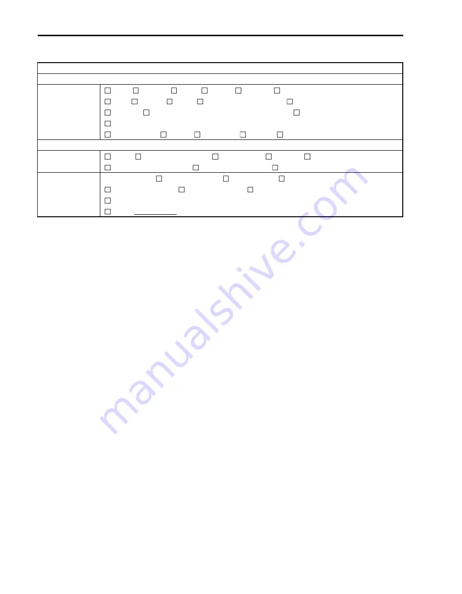
VEHICLE/ENVIRONMENTAL CONDITION WHEN PROBLEM OCCURS
Environmental condition
Weather
Temperature
Frequency
Fair
Cloudy
Rain
Snow
Always
Other
Hot
Warm
Cool
Cold ( °F/ °C)
Always
Always
Sometimes ( times/ day, month)
Only once
Under certain condition
Road
Mountainous (
Uphill
Downhill)
Gravel
Other
Vehicle condition
Engine condition
Cold
Warming up phase
Warmed up
Always
Other at starting
Immediately after start
Racing without load
Engine speed ( r/min)
Vehicle condi-
tion
During driving:
Constant speed
Accelerating
Decelerating
Right hand corner
Left hand corner
At stop
Vehicle speed when problem occurs ( km/h, Mile/h)
Other
Summary of Contents for LT-A700X 2004
Page 25: ...2 8 PERIODIC MAINTENANCE INTAKE SIDE ...
Page 26: ...PERIODIC MAINTENANCE 2 9 EXHAUST SIDE ...
Page 46: ...PERIODIC MAINTENANCE 2 29 ...
Page 59: ...3 8 ENGINE Remove the engine from the right side ...
Page 133: ...3 82 ENGINE Pull the rope and check that the ratchet is pushed out ...
Page 155: ......
Page 263: ......
Page 301: ...7 20 COOLING AND LUBRICATION SYSTEM EXHAUST SIDE INTAKE SIDE ...
Page 302: ......
Page 312: ...CHASSIS 8 9 REAR CARRIER Remove the rear carrier 1 ...
Page 386: ......
Page 420: ...ELECTRICAL SYSTEM 9 33 HEADLIGHT INSTALLATION Head light coupler Head light R Adjusting point ...
Page 453: ...10 26 SERVICING INFORMATION Rear box Rear fender Right mud guard Left mud guard ...
Page 477: ......
Page 480: ...Prepared by September 2004 Part No 99500 46060 01E Printed in U S A 472 ...


