FI SYSTEM DIAGNOSIS 5-21
SELF-DIAGNOSTIC PROCEDURES
NOTE:
* Don’t disconnect the coupler from ECM, the battery cable from
the battery, before confirming the malfunction code (self-diag-
nostic trouble code) stored in the memory. Such disconnection
will erase the memorized information in ECM memory.
* Malfunction code stored in ECM memory can be checked by
the special tool.
* Before checking malfunction code, read SELF-DIAGNOSIS
FUNCTION “USER MODE and DEALER MODE” (
$
5-14)
carefully to have good understanding what functions are avail-
able and how to use it.
* Be sure to read “PRECAUTIONS for Electrical Circuit Service”
(
$
5-2) before inspection and observe what is written there.
• Remove the seat. (
$
8-4)
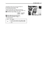
• Connect the special tool to the dealer mode coupler
A
at the
wiring harness, and start the engine or crank the engine for
more than 4 seconds.
• Turn the special tool’s switch to ON and check the malfunc-
tion code to determine the malfunction part.
%
09930-82720: Mode select switch
Summary of Contents for LT-A700X 2004
Page 25: ...2 8 PERIODIC MAINTENANCE INTAKE SIDE ...
Page 26: ...PERIODIC MAINTENANCE 2 9 EXHAUST SIDE ...
Page 46: ...PERIODIC MAINTENANCE 2 29 ...
Page 59: ...3 8 ENGINE Remove the engine from the right side ...
Page 133: ...3 82 ENGINE Pull the rope and check that the ratchet is pushed out ...
Page 155: ......
Page 263: ......
Page 301: ...7 20 COOLING AND LUBRICATION SYSTEM EXHAUST SIDE INTAKE SIDE ...
Page 302: ......
Page 312: ...CHASSIS 8 9 REAR CARRIER Remove the rear carrier 1 ...
Page 386: ......
Page 420: ...ELECTRICAL SYSTEM 9 33 HEADLIGHT INSTALLATION Head light coupler Head light R Adjusting point ...
Page 453: ...10 26 SERVICING INFORMATION Rear box Rear fender Right mud guard Left mud guard ...
Page 477: ......
Page 480: ...Prepared by September 2004 Part No 99500 46060 01E Printed in U S A 472 ...


