5-54 FI SYSTEM DIAGNOSIS
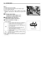
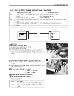
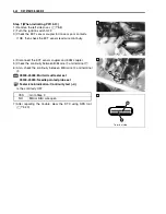
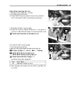
Step 1 (When indicating P1651-L:)
1) Remove the side covers. (
$
8-8)
2) Turn the ignition switch OFF.
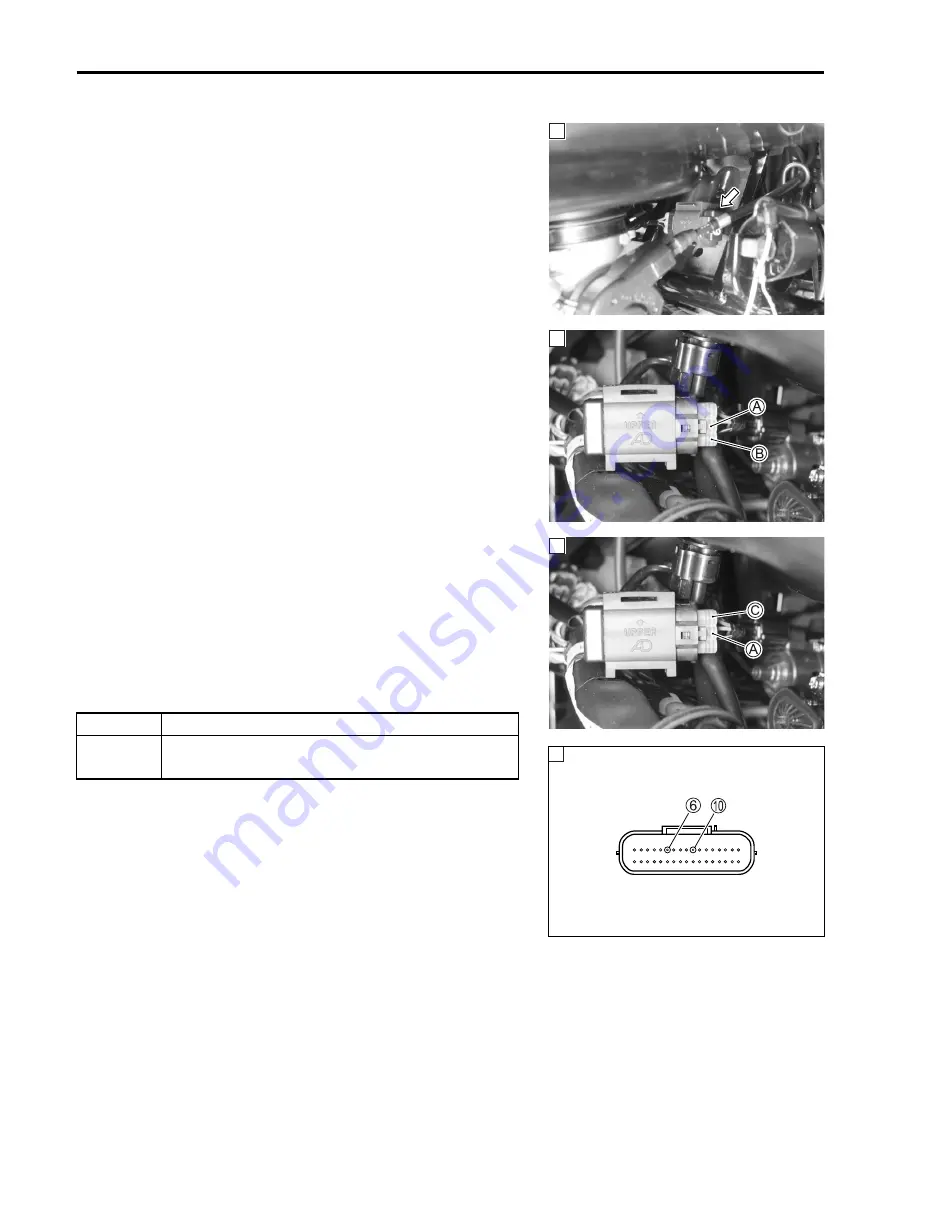
3) Check the TO sensor coupler for loose or poor contacts.
If OK, then check the TO sensor lead wire continuity.
4) Remove the TO sensor.
5) Disconnect the TO sensor coupler.
6) Check the continuity between Br/W wire
A
and ground.
7) Also, check the continuity between Br/W wire
A
and B/Br
wire
B
. If sound is not heard from the tester, the circuit condi-
tion is OK.
8) Disconnect the ECM coupler.
9) Check the continuity between Red wire
C
and terminal
6
.
10) Also, check the continuity between Br/W wire
A
and termi-
nal
0
.
%
09900-25008: Multi-circuit tester set
09900-25009: Needle pointed probe set
7
Tester knob indication: Continuity test (
6
)
Is the continuity OK?
11) After repairing the trouble, clear the DTC using SDS tool.
(
$
5-23)
1
1
YES
Go to Step 2.
NO
Red or Br/W wire open, or Br/W wire shorted to
ground.
1
1
Terminal side
Summary of Contents for LT-A700X 2004
Page 25: ...2 8 PERIODIC MAINTENANCE INTAKE SIDE ...
Page 26: ...PERIODIC MAINTENANCE 2 9 EXHAUST SIDE ...
Page 46: ...PERIODIC MAINTENANCE 2 29 ...
Page 59: ...3 8 ENGINE Remove the engine from the right side ...
Page 133: ...3 82 ENGINE Pull the rope and check that the ratchet is pushed out ...
Page 155: ......
Page 263: ......
Page 301: ...7 20 COOLING AND LUBRICATION SYSTEM EXHAUST SIDE INTAKE SIDE ...
Page 302: ......
Page 312: ...CHASSIS 8 9 REAR CARRIER Remove the rear carrier 1 ...
Page 386: ......
Page 420: ...ELECTRICAL SYSTEM 9 33 HEADLIGHT INSTALLATION Head light coupler Head light R Adjusting point ...
Page 453: ...10 26 SERVICING INFORMATION Rear box Rear fender Right mud guard Left mud guard ...
Page 477: ......
Page 480: ...Prepared by September 2004 Part No 99500 46060 01E Printed in U S A 472 ...

