CHASSIS 8-21
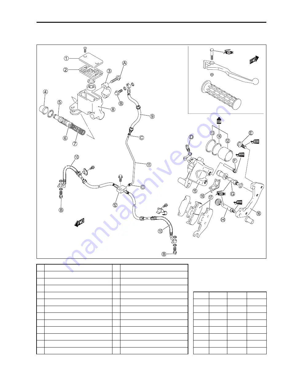
FRONT BRAKE
CONSTRUCTION
1
Master cylinder reservior cap
D
Dust seal
2
Diaphragm
E
Brake caliper
3
Master cylinder clamp
F
Brake caliper holder
4
Boot
G
Brake pad
#
5
Piston/cup set
H
Pad spring
ITEM
N·m
kgf-m
lb-ft
6
Cup
A
Master cylinder clamp bolt
A
10
1.0
7.0
7
Spring
B
Brake hose union bolt
B
23
2.3
16.5
8
Master cylinder
C
Brake pipe nut
C
16
1.6
11.5
9
Brake hose No.1
D
Air bleeder valve
D
5.5
0.55
4.0
0
Brake hose No.2
E
Brake caliper mounting bolt
E
26
2.6
19.0
A
Brake pipe
F
Brake pad mounting pin
F
18
1.8
13.0
B
Piston
G
Caliper holder pin
G
18
1.8
13.0
C
Piston seal
H
Calipr holder slide pin
H
23
2.3
16.5
Summary of Contents for LT-A700X 2004
Page 25: ...2 8 PERIODIC MAINTENANCE INTAKE SIDE ...
Page 26: ...PERIODIC MAINTENANCE 2 9 EXHAUST SIDE ...
Page 46: ...PERIODIC MAINTENANCE 2 29 ...
Page 59: ...3 8 ENGINE Remove the engine from the right side ...
Page 133: ...3 82 ENGINE Pull the rope and check that the ratchet is pushed out ...
Page 155: ......
Page 263: ......
Page 301: ...7 20 COOLING AND LUBRICATION SYSTEM EXHAUST SIDE INTAKE SIDE ...
Page 302: ......
Page 312: ...CHASSIS 8 9 REAR CARRIER Remove the rear carrier 1 ...
Page 386: ......
Page 420: ...ELECTRICAL SYSTEM 9 33 HEADLIGHT INSTALLATION Head light coupler Head light R Adjusting point ...
Page 453: ...10 26 SERVICING INFORMATION Rear box Rear fender Right mud guard Left mud guard ...
Page 477: ......
Page 480: ...Prepared by September 2004 Part No 99500 46060 01E Printed in U S A 472 ...


