ELECTRICAL SYSTEM 9-19
INSPECTION
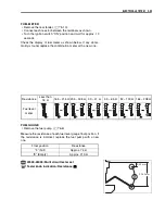
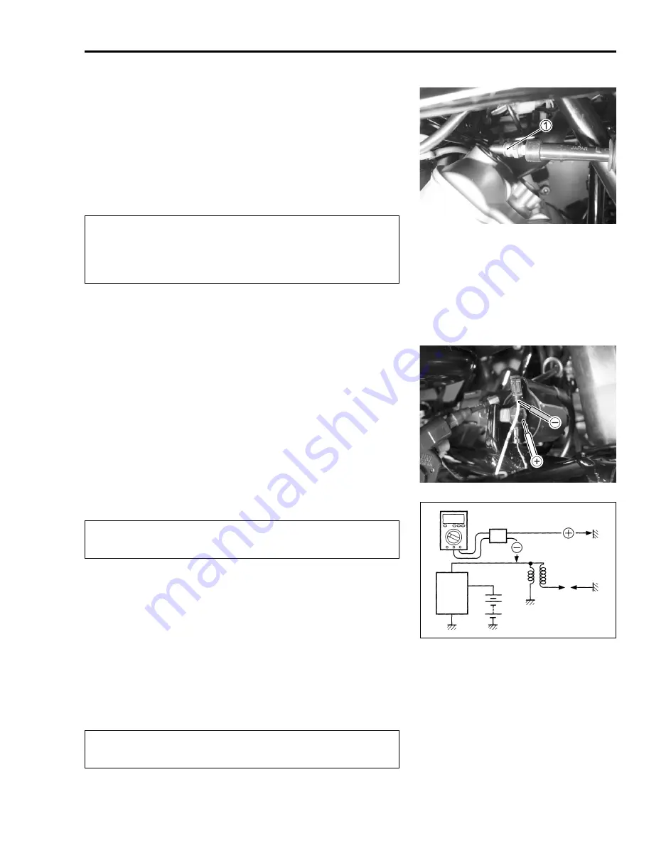
IGNITION COIL PRIMARY PEAK VOLTAGE
• Remove the right side cover. (
!
8-8)
• Remove the right inner fender. (
!
8-6)
• Remove the spark plug cap.
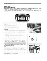
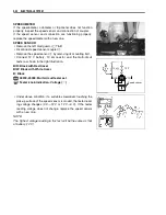
• Connect a new spark plug
1
to spark plug cap and ground it
to the cylinder head cover bolt.
#
NOTE:
Make sure that the spark plug cap and spark plug are connected
properly and the battery is fully-charged.
Measure ignition coil primary peak voltage with the multi-circuit
tester in the following procedure.
• Connect the multi-circuit tester with the peak voltage adaptor
as follows.
+
Probe: Black/White lead wire or ground
-
Probe: White/Blue lead wire
NOTE:
Do not disconnect the ignition coil primary wire.
"
09900-25008: Multi-circuit tester set
#
• Shift the transfer to the neutral position and turn the ignition
switch to the “ON” position.
• Press the starter button and allow the engine to crank for a
few seconds, and then measure the ignition coil primary peak
voltage.
• Repeat the above procedure a few times and measure the
highest ignition coil primary peak voltage.
'
Tester knob indication: Voltage (
%
)
&
Ignition coil primary peak voltage: More than 80 V
0
If the voltage is lower than the standard values, inspect the igni-
tion coil. (
!
9-20)
Avoid grounding the spark plug and suppling the elec-
trical shock to the cylinder head cover (magnesium
parts) to prevent the magnesium material from dam-
age.
When using the multi-circuit tester and peak volt
adaptor, refer to the appropriate instruction manual.
While testing, do not touch the tester probes and
spark plug to prevent receiving an electric shock.
Peak volt adaptor
CDI
unit
Battery
New spark plug
Ignition
coil
Summary of Contents for LT-A700X 2004
Page 25: ...2 8 PERIODIC MAINTENANCE INTAKE SIDE ...
Page 26: ...PERIODIC MAINTENANCE 2 9 EXHAUST SIDE ...
Page 46: ...PERIODIC MAINTENANCE 2 29 ...
Page 59: ...3 8 ENGINE Remove the engine from the right side ...
Page 133: ...3 82 ENGINE Pull the rope and check that the ratchet is pushed out ...
Page 155: ......
Page 263: ......
Page 301: ...7 20 COOLING AND LUBRICATION SYSTEM EXHAUST SIDE INTAKE SIDE ...
Page 302: ......
Page 312: ...CHASSIS 8 9 REAR CARRIER Remove the rear carrier 1 ...
Page 386: ......
Page 420: ...ELECTRICAL SYSTEM 9 33 HEADLIGHT INSTALLATION Head light coupler Head light R Adjusting point ...
Page 453: ...10 26 SERVICING INFORMATION Rear box Rear fender Right mud guard Left mud guard ...
Page 477: ......
Page 480: ...Prepared by September 2004 Part No 99500 46060 01E Printed in U S A 472 ...


