ENGINE 3-33
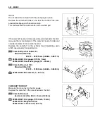
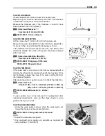
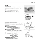
VALVE FACE WEAR
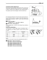
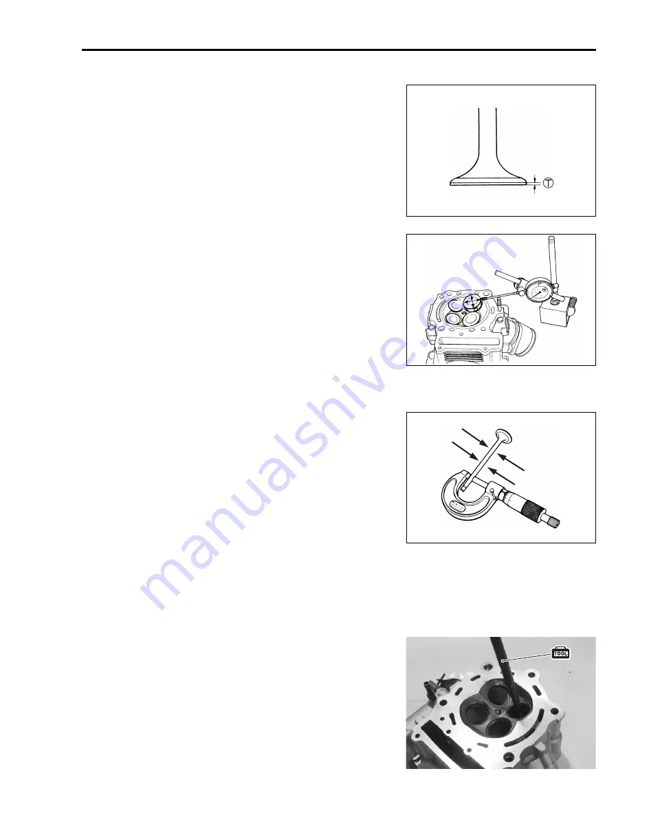
Visually inspect each valve for wear of its seating face.
Replace any valve with an abnormally worn face. The thickness
T
decreases as the wear of the face advances.
Measure the thickness and, if the thickness is found to have
been reduced to the limit, replace it.
&
Valve head thickness
T
:
Service Limit: 0.5 mm (0.02 in)
%
09900-20101: Vernier calipers
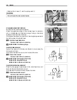
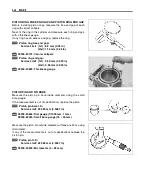
VALVE STEM DEFLECTION
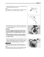
Lift the valve about 10 mm (0.39 in) from the valve seat.
Measure the valve stem deflection in two directions, perpendicu-
lar to each other, by positioning the dial gauge as shown.
If the deflection measured exceeds the limit, (see below) then
determine whether the valve or the guide should be replaced
with a new one.
&
Valve stem deflection (IN & EX):
Service Limit: 0.35 mm (0.014 in)
%
09900-20607: Dial gauge (1/100 mm)
09900-20701: Magnetic stand
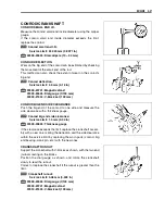
VALVE STEM WEAR
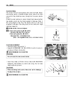
If the valve stem is worn down to the limit, as measured with a
micrometer, where the clearance is found to be in excess of the
limit indicated, replace the valve; if the stem is within the limit,
then replace the guide.
After replacing valve or guide, be sure to recheck the deflection.
&
Valve stem O.D.:
Standard (IN) : 5.475 – 5.490 mm (0.2156 – 0.2161 in)
(EX) : 5.455 – 5.470 mm (0.2148 – 0.2154 in)
%
09900-20205: Micrometer (0 – 25 mm)
NOTE:
If valve guides have to be removed for replacement after
inspecting related parts, carry out the steps shown in valve
guide servicing. (
$
3-33)
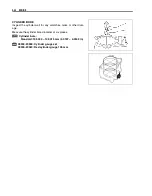
VALVE GUIDE SERVICING
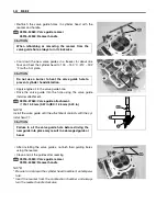
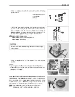
• Using the valve guide remover, drive the valve guide out
toward the intake or exhaust camshaft side.
%
09916-44910: Valve guide installer/remover
NOTE:
* Discard the removed valve guide.
* Only oversized valve guides are available as replacement
parts. (Part No.11115-31G70)
Summary of Contents for LT-A700X 2004
Page 25: ...2 8 PERIODIC MAINTENANCE INTAKE SIDE ...
Page 26: ...PERIODIC MAINTENANCE 2 9 EXHAUST SIDE ...
Page 46: ...PERIODIC MAINTENANCE 2 29 ...
Page 59: ...3 8 ENGINE Remove the engine from the right side ...
Page 133: ...3 82 ENGINE Pull the rope and check that the ratchet is pushed out ...
Page 155: ......
Page 263: ......
Page 301: ...7 20 COOLING AND LUBRICATION SYSTEM EXHAUST SIDE INTAKE SIDE ...
Page 302: ......
Page 312: ...CHASSIS 8 9 REAR CARRIER Remove the rear carrier 1 ...
Page 386: ......
Page 420: ...ELECTRICAL SYSTEM 9 33 HEADLIGHT INSTALLATION Head light coupler Head light R Adjusting point ...
Page 453: ...10 26 SERVICING INFORMATION Rear box Rear fender Right mud guard Left mud guard ...
Page 477: ......
Page 480: ...Prepared by September 2004 Part No 99500 46060 01E Printed in U S A 472 ...

