COOLING AND LUBRICATION SYSTEM 7-9
ECT SENSOR
REMOVAL
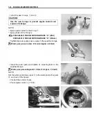
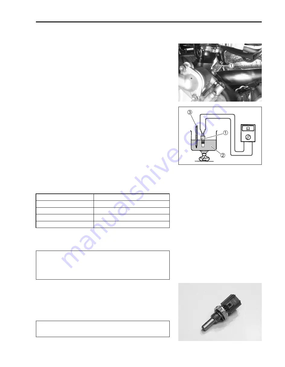
• Remove the left side cover. (
$
8-8)
• Disconnect the ECT sensor coupler
1
.
• Place a rag under the ECT sensor and remove the ECT sen-
sor.
INSPECTION
Check the ECT sensor by testing it at the bench as shown in the
figure. Connect the ECT sensor
1
to a circuit tester and place it
in the oil
2
contained in a pan, which is placed on a stove.
Heat the oil to raise its temperature slowly and read the column
thermometer
3
and the ohmmeter.
If the ECT sensor ohmic value does not change in the proportion
indicated, replace it with a new one.
&
Temperature sensor specification
If the resistance is noted to show infinity or too much different
resistance value, replace the ECT sensor with a new one.
#
INSTALLATION
• Install the ECT sensor in the reverse order of removal.
• Tighten the ECT sensor to the specified torque.
"
ECT sensor: 18 N·m (1.8 kgf-m, 13.0 lb-ft)
#
• Pour engine coolant. (
$
2-16)
Temperature
Standard resistance
20 °C (68 °F)
Approx. 2.45 k
Ω
50 °C (122 °F)
Approx. 0.811 k
Ω
80 °C (176 °F)
Approx. 0.318 k
Ω
110 °C (230 °F)
Approx. 0.142 k
Ω
* Take special care when handling the ECT sensor. It
may cause damage if it gets a sharp impact.
* Do not contact the ECT sensor and the column ther-
mometer with a pan.
Take special care when handling the ECT sensor. It
may cause damage if it gets a sharp impact.
Summary of Contents for LT-A700X 2004
Page 25: ...2 8 PERIODIC MAINTENANCE INTAKE SIDE ...
Page 26: ...PERIODIC MAINTENANCE 2 9 EXHAUST SIDE ...
Page 46: ...PERIODIC MAINTENANCE 2 29 ...
Page 59: ...3 8 ENGINE Remove the engine from the right side ...
Page 133: ...3 82 ENGINE Pull the rope and check that the ratchet is pushed out ...
Page 155: ......
Page 263: ......
Page 301: ...7 20 COOLING AND LUBRICATION SYSTEM EXHAUST SIDE INTAKE SIDE ...
Page 302: ......
Page 312: ...CHASSIS 8 9 REAR CARRIER Remove the rear carrier 1 ...
Page 386: ......
Page 420: ...ELECTRICAL SYSTEM 9 33 HEADLIGHT INSTALLATION Head light coupler Head light R Adjusting point ...
Page 453: ...10 26 SERVICING INFORMATION Rear box Rear fender Right mud guard Left mud guard ...
Page 477: ......
Page 480: ...Prepared by September 2004 Part No 99500 46060 01E Printed in U S A 472 ...


