ENGINE 3-39
CLUTCH SHOE/MOVABLE DRIVEN FACE
DISASSEMBLY
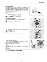
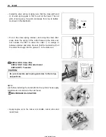
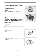
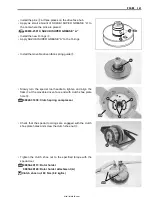
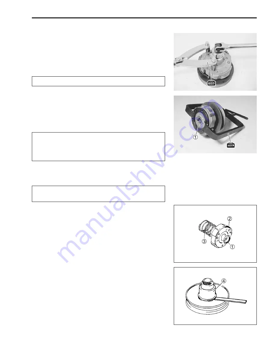
• Loosen the clutch shoe nut with the special tool.
$
09930-40113: Rotor holder
09930-40120: Rotor holder attachment (A)
#
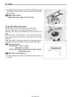
• Lock the clutch shoe assembly with the special tool handle
turned in.
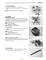
• Remove the clutch shoe nut
1
.
$
09922-31430: Clutch spring compressor
#
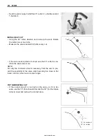
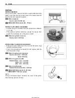
• Loosen the special tool handle slowly and remove the clutch
shoe assembly.
#
1
Nut
2
Clutch shoe assembly
3
Spring
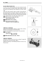
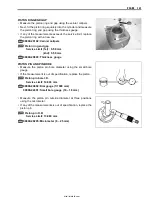
• Remove the movable driven face seat
4
with a thin blade
screwdriver.
Do not remove the clutch shoe nut at this time.
Since a high spring force applies to the clutch shoe
assembly, care must be used so as not to cause the
clutch shoe assembly and movable driven face to
come off abruptly.
Do not attempt to disassemble the clutch shoe assem-
bly.
http://mototh.com
Summary of Contents for UY125
Page 4: ...White Page http mototh com ...
Page 12: ...White Page http mototh com ...
Page 31: ...PERIODIC MAINTENANCE 2 19 http mototh com ...
Page 108: ...White Page http mototh com ...
Page 183: ...ELECTRICAL SYSTEM 6 7 8 Ignition coil 9 Starter relay 0 Starter motor http mototh com ...
Page 214: ...White Page http mototh com ...
Page 244: ...7 30 SERVICING INFORMATION FRONT WHEEL UY125 5 J _ http mototh com ...
Page 245: ...SERVICING INFORMATION 7 31 FRONT WHEEL UY125S Clearance 1 mm http mototh com ...
Page 246: ...7 32 SERVICING INFORMATION REAR WHEEL http mototh com ...

