SVAN 948 USER MANUAL
5 - 23
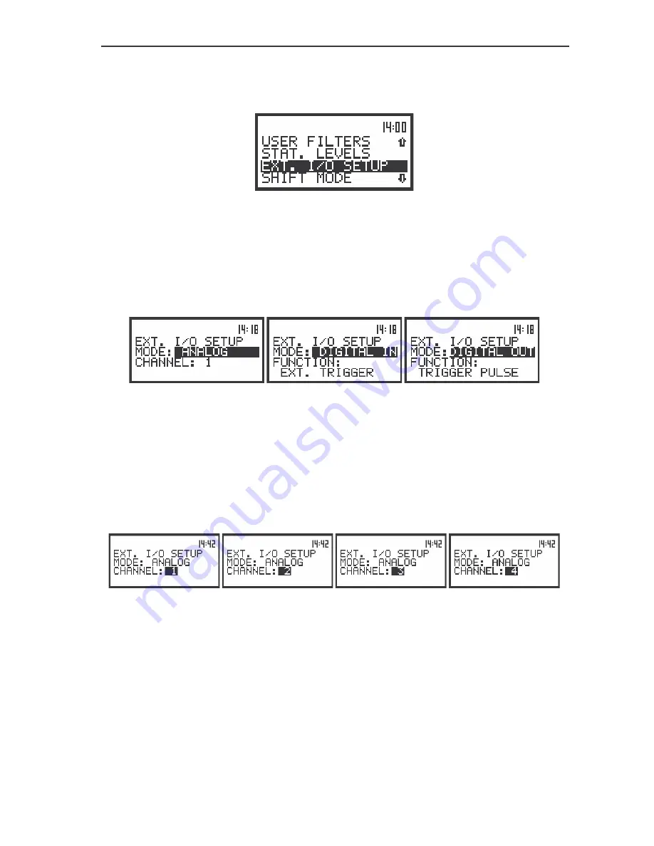
This position enables the user to set the proper external device. In order to enter this position the
user has to select the
EXT. I/O SETUP
text in the
SETUP
list, using the
<
>
,
<
>
(or
<
>
,
<
>
) push-
buttons, and press the
<ENTER>
.
The view of the display in the
SETUP
list in sound measurements, the EXT. I/O SETUP text highlighted
(displayed inversely)
In the
MODE
position of
EXT. I/O SETUP
sub-list three options are available:
ANALOG
,
DIGITAL IN
and
DIGITAL OUT
. In order to select the external device user has to press the
<
>
,
<
>
push-buttons. The position is closed and the instrument returns to the
SETUP
list after pressing the
<ENTER>
(with the confirmation of a change made in the position) or
<ESC>
push-button (ignoring a
change made in the position).
The displays in the EXT. I/O SETUP position, the selection different I/O devices
•
ANALOG
– in this mode the meter can give signals to the output device. For example the signal
can be observed on the oscilloscope from the selected CHANNEL. The user has
possibility to choose between
CHANNEL 1, 2, 3 and 4.
The channel position enables the user to set the external channel. In order to enter this position the
user has to select the
CHANNEL
text in the
EXT. I/O SETUP
list, using the
<
>
,
<
>
push-buttons.
After selection of the
CHANNEL
the user has to press the
<
>
,
<
>
push-buttons. The position is closed
and the instrument returns to the
SETUP
list after pressing the
<ENTER>
(with the confirmation of a
change made in the position) or
<ESC>
push-button (ignoring a change made in the position).
The displays in the EXT. I/O SETUP position, the channel selection for output signal
•
DIGITAL IN
– in this mode the meter is connected to the output device which triggers it to
undertake measurements. It starts to measure, when on its input there is a triggering
impulse. In this mode the instrument works in
EXT.TRIGGER
function.
•
DIGITAL OUT
– in this mode the meter is connected to output device which is triggers by meter to
measure. It sends digital trigger pulse to another device. In this mode the instrument
works in
TRIGGER PULSE
function.
It is especially important, when the user wants to measure the noise or vibration in more
then 4 channels simultaneously. In this connection both instruments works synchronized.
Summary of Contents for SVAN 948
Page 1: ...SVAN 948 SOUND AND VIBRATION DATA LOGGER USER S MANUAL SVANTEK Sp z o o WARSAW June 2004...
Page 19: ...SVAN 948 USER MANUAL 2 6 The view of the rear panel of the SVAN 948 instrument in 1 1 scale...
Page 25: ...SVAN 948 USER MANUAL 3 6 Control diagram of the INPUT list...
Page 28: ...SVAN 948 USER MANUAL 3 9 Control diagram of the DISPLAY list...
Page 30: ...SVAN 948 USER MANUAL 3 11 Control diagram of the FILE list...
Page 32: ...SVAN 948 USER MANUAL 3 13 Control diagram of the AUX FUNCTION list...
Page 36: ...SVAN 948 USER MANUAL 3 17...
Page 37: ...SVAN 948 USER MANUAL 3 18 Control diagram of the SETUP list...


