E 3
E
DF 1
15/
135C.
G
B
3
-6 -
02-
01.
03
2.3
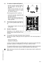
For hydraulic adjustment (Optional)
- Note the currently adjusted height of
the screed beam - left and right - on
the scale.
- Push or pull the switches (2) on the
operating panel to retract or extend
the hydraulic cylinders.
(Pavers eguiped with PLC system o)
- Activate the spreader adjustment with
the push button (2).
- With the push buttons (3) and (4), re-
tract or extend the right and left hy-
draulic cylinders.
$
Actuate the push buttons simultaneous-
ly, so that the spreader beam does not
tilt.
- Check that the height on the left right
corresponds.
2.4
Spreader enlargement
Depending on the particular type of
screed, diverse operating widths can be
achieved.
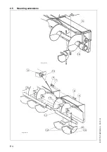
The spreader and screed enlargement must correspond.
See also the chapter ”Setting-up and field replacement” in the screed operating in-
structions:
- Screed mounting plan
- Spreader mounting plan
In order to achieve the required operating width, the respective screed extensions,
side plates, spreaders, tunnel plates or cut off shoes must be mounted.
For operating widths above 3.00 m, the distribution spreader should be provided with
an extension on each side to improve material distribution and reduce wear.
When carrying out all work on the spreader, the diesel engine must be switched off.
Risk of injury!
2
2
7.eps/Element1_SPS.cdr
4
2
3
2
Summary of Contents for DF 115 C
Page 1: ...Operating instructions 02 01 03 Road Finisher 900 98 06 40 DF 115 C DF 135 C...
Page 2: ......
Page 4: ......
Page 10: ......
Page 12: ......
Page 40: ......
Page 44: ...D 4 D D_DF115_135C_GB fm 4 92 02 01 03 Element2_KC cdr 9 8 12 A 9 A 5 6 7 11 10...
Page 46: ...D 6 D D_DF115_135C_GB fm 6 92 02 01 03 Element2_KC cdr 9 8 12 A 9 A 5 6 7 11 10...
Page 132: ......
Page 178: ......

