background image

Operating instructions

02-0103

Paver Finisher

900 98 06 33

DF 115 P
DF 135 P

Summary of Contents for DF 115 P

Page 1: ...Operating instructions 02 0103 Paver Finisher 900 98 06 33 DF 115 P DF 135 P ...

Page 2: ......

Page 3: ... machine option is used Safety instructions and important notes are identified by the following pictograms Precedes safety instructions that must be observed in order to prevent danger to per sonnel Precedes notes that must be observed to prevent damage to equipment Precedes general notes and explanations Used to indicate standard equipment Used to indicate optional equipment In the interest of co...

Page 4: ......

Page 5: ...ices 8 4 Technical data standard type 9 4 1 Performance data 9 4 2 Final drive track group 9 4 3 Engine 9 4 4 Hydraulic system 10 4 5 Hopper trough 10 4 6 Weights all values in t 10 4 7 Material feed 11 4 8 Material distribution 11 4 9 Screed lift 11 4 10 Electrical equipment 11 5 EN standards 13 5 1 Continuous sound pressure level 13 5 2 Operating conditions during measurements 13 5 3 Measuring p...

Page 6: ...the left and the right beneath the driver s seat 74 25 Seat lock behind the driver s seat 75 26 Service brake foot brake 76 26 Parking brake hand brake 77 26 Switch lever for two speed transmission 78 27 Switch lever for the differential lock 79 27 Separator fluid spraying system 80 o 28 Locking of the collapsible roof LH and RH on the roofs console 87 28 Electrical adjustment of the conveyor perf...

Page 7: ... Direction marks 41 Loading distributing material 42 3 4 Starting for paving 44 3 5 Checks during paving 46 Paver function 46 Quality of the layer 46 3 6 Paving with screed stop and screed charging relieving 47 General 47 Screed charging relieving 47 Screed stop 47 Screed stop with pretensioning 48 Adjusting the pressure 48 Adjusting the pressure for screed charging relieving 49 Adjusting the pres...

Page 8: ...r every 100 operating hours 8 2 6 Monthly or every 250 operating hours 9 2 7 Every 3 months or every 500 operating hours 10 2 8 Annually or every 1000 operating hours 11 2 9 Every 2 years or every 2000 operating hours 12 2 10 If necessary 13 2 11 Inspection and lubrication points 14 Pump distributor gear 1 1 14 Lubricating oil engine 1 2 15 Oil level check 15 Oil change 15 Engine oil filter 1 3 16...

Page 9: ...nveyor drive transmission 4 3 29 Auger planetary gear 4 4 30 Conveyor auger drive chains 4 5 31 Auger box 4 6 32 Outer auger bearing 4 7 33 Visual inspections 5 1 33 Crossbeam guide 5 2 33 Nuts and bolts 5 3 34 Tightening torques 34 Moving parts 5 4 34 Hydraulic screw connections 5 5 34 Battery 6 1 35 3 Fuels and lubricants 36 3 1 Hydraulic oils 37 3 2 Capacities 38 3 3 Tyre inflation pressure 38 ...

Page 10: ......

Page 11: ...thin the meaning of the present operating instructions is defined as any natural or legal person who either uses the paver finisher himself or on whose behalf it is used In special cases e g leasing or renting the user is considered the person who in accordance with existing contractual agreements between the owner and the user of the paver finisher is charged with the observance of the operating ...

Page 12: ......

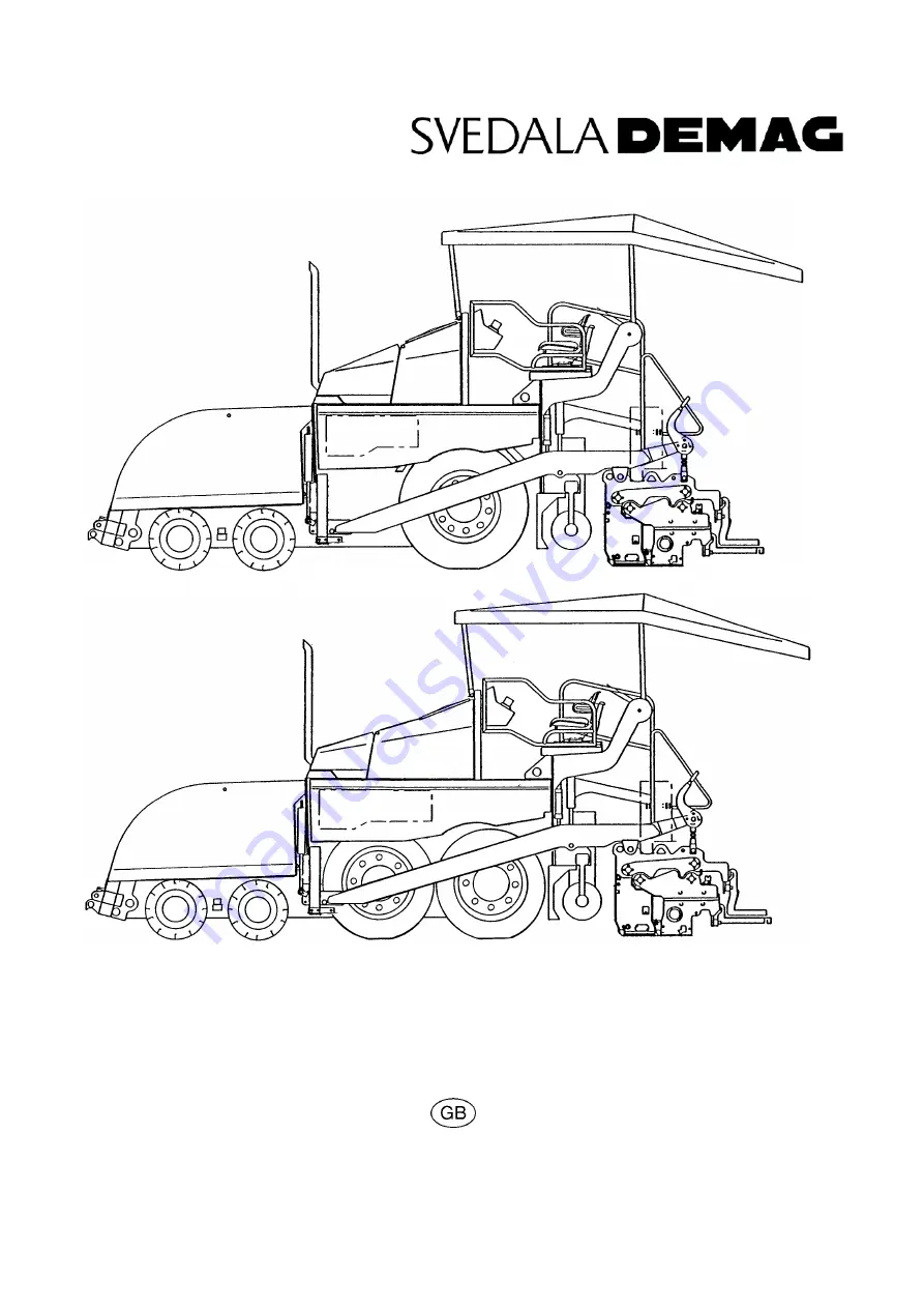
Page 13: ...ption 1 Description of application The SVEDALA DEMAG road finisher is equipped with a crawler for laying bituminous material rolled or lean mixes concrete track ballast and uncombined mineral com pounds for paving surfaces Df_115_p tif Df_135_p tif ...

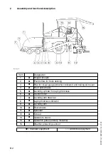
Page 14: ...d trailing ski mount 4 Front axle wheels 5 Levelling cylinder for laying thickness 6 Traction roller 7 Levelling arm draw bar 8 Laying thickness indicator 9 Levelling arm 10 Rear wheels 11 Spreader 12 Screed 13 Operator s stand 14 Operation panel laterally movable 15 Weather protecting sunroof Standard equipment Additional equipment Df_115_p tif 9 8 6 5 3 2 10 12 11 4 14 13 15 1 7 ...

Page 15: ...p Hydraulic spreader height adjustment Weather protection shed weather protecting sunroof Screed enlargement Screed vibration system Generator Special paint finish Automatic levelling system and accessories Other accessories such as edge compactor floodlight level trailing shoe Available as special accessories optional Two front wheel drive with anti spin Four front wheel drive with anti spin Two ...

Page 16: ...can be adjusted The finisher is pushed less off course laying on bends is fa cilitated Hopper trough The trough inlet is provided with a flight bar conveyor system for discharge and further transport to the distribution spreader The capacity is about 13 0 t For improved discharge and uniform material feed each of the side covers of the trough can be folded hydraulically optional Material feed The ...

Page 17: ...ion angle traction roller lift the laying thickness of the material or skimming level of the screed can be controlled Actuation takes place on both sides electro hydraulically and can take place either manually via a toggle switch or automatically via an electronic grade transmitter Screed hoist The screed hoist serves for lifting the screed for transport purposes Hoisting takes place on both side...

Page 18: ...ton on operation panel on both remotes optional When the emergency button is pressed motor drives and steering are deactivat ed any necessary countermeasures such as manoeuvring screed lifting and similar are no longer possible Risk of accident 3 2 Steering The finisher is steered with the steering wheel 3 3 Ignition lock lighting equipment The lighting can be switched on and off by turning the ig...

Page 19: ...wer switch is located on the right hand side of the paver finisher between the central panel and hopper 3 7 Trough safety lock 3 8 Screed safety lock The screed safety locks are provided on both sides on the operation panel behind the seats Horn tif Horn_k cdr F0077_a1 eps F0076A_A1 eps F0083_a1 tif ...

Page 20: ... 8 18 01 03 3 9 Other safety devices Other equipment Wedges Item Designation 23 Engine covers 24 Side flaps 25 Catwalks 26 Screed covers 27 Material duct 28 Screed hazard lights 23 28 24 27 26 25 Df_115_p tif Df_135_p tif ...

Page 21: ...ickness 300 mm Max Particle size 40 mm Theoretical laydown rate DF115P 600 t h Theoretical laydown rate DF135P 700 t h Drive Hydrostatic drive infinitely variable speed Track group Two individually driven crawlers with rubber pad track groups Speed see above Wheels rear Fülldruck 13 R 22 5 4 5 8 0 bar 14 00 R 25 XGC 4 0 bar 4 0 bar Make Type Deutz BF6M 2012 EC Design 6 cylinder diesel engine water...

Page 22: ...al drive Material feed and distribution Tamper vibration optional Cylinder actuating elements for trough levelling screed lift screed extend retract Spreader lift optional Downstream compressor optional Hydraulic oil tank capacity see Chapter F Capacity ca 6 m about 13 t Minimum inlet height centre 480 mm Minimum inlet height external 600 mm Finisher without screed about 14 0 t Finisher with scree...

Page 23: ...t of flight bar conveyor spreader halves switchable for operation in opposite directions Flow control Fully automatic via adjustable switching points Spreader lift mechanical optional hydraulic Spreader enlargement With extension sections see spreader mounting diagram Special functions When stationary Screed stop Screed stop with preloading max pressure 50 bar When laying Screed load Screed releas...

Page 24: ...and tail pipe 2610 2610 D Trough height trough fully closed 2040 2040 E Operation panel height 1600 1600 F Hopper length 2100 2100 G Dumping 1950 1950 H Distance of push roller front wheel 740 740 I Distance of second front wheel rear wheel 1990 1310 I2 Distance between front wheels 875 875 I3 Distance between rear wheels only 135P 1200 J Spreader diameter 380 380 K Length without screed catwalk w...

Page 25: ... 84 5 dB A DF115P Sound capacity level LWA 107 0 dB A DF135P Sound capacity level LWA 108 7 dB A Sound pressure level at the machine 5 2 Operating conditions during measurements The diesel engine operated at maximum speed Flight bar conveyors spreaders tampers and vibration arrangement operated at minimum of 50 of their maximum speed 5 3 Measuring point arrangement Semi spherical measuring surface...

Page 26: ...ab of ahw 2 5 m s according to the draft standard prEN 1033 1995 are not exceeded Emitted interference according to DIN EN 50081 1 03 93 40 dB µV m for frequencies from 30 MHz 230 MHz at a measuring distance of 3 m 47 dB µV m for frequencies from 20 MHz 1 GHz at a measuring distance of 3 m Immunity to electrostatic discharge ESD according to DIN EN 61000 4 2 03 96 4 KV contact and 8 KV air dischar...

Page 27: ...ompletion of work with extinguishing of the burner and in case of fires the cylinder valves must be closed immediately 6 To be observed when igniting the burner 1 Open cylinder valves and main shut off valve Press hose protection for several seconds 2 Turn ignition key and switch on power supply with separate switch 3 Troubleshooting should be carried out only by the supervisor Observe operating i...

Page 28: ...ck for diesel fuel 4 Sign Filler neck for hydraulic oil 5 Sign Close safety valve immediately 6 Sign Attention Standing in the operating area 7 Sign Check hydraulic oil level 8 Sign Hearing protection 9 Sign Safety information on gas system Signs under engine hood Signs on both sides of finisher Sign on operation panel ...

Page 29: ...isher type 48 Year of manufacture 49 Serial number of finisher series 50 Maximum permissible operating weight including all extension sections in kg 51 Maximum possible load on front axle in kg 52 Maximum permissible load on rear axle in kg 53 Rated power in kW 47 51 50 48 54 52 49 53 ...

Page 30: ...2 Item Designation 55 Year of manufacture 56 Type of gas to be used 57 Inlet pressure in bar 58 Average gas consumption of mounted screed in kg h Liquefied petroleum gas system Year of manufacture Propane Propane Inlet pressure 1 5 bar Connected load per burner 1 5 Kg h 55 56 57 58 ...

Page 31: ... boxes and into the hopper Close all coverings and check that they are securely seated In Germany gas bottles must not be transported on the paver finisher or on the screed Disconnect the gas bottles from the gas system and protect them with their caps Use a separate vehicle to transport them When loading via ramps the paver finisher may slip aside tilt or topple over Drive carefully Keep the dang...

Page 32: ...es 7 downward un til the leveling cylinders are com pletely extended Set the drive lever 6 to the center position Retract the screed parts until the screed matches the basic width of the paver finisher Remove all protruding or loose parts from the paver finisher and the screed see also the operating instructions for the screed Store these parts in a safe place When screed is operated with the op t...

Page 33: ... finisher to the low bed trailer Use only appropriate approved at tachment devices Use the four securing points provid ed 1 2 Wait until the exhaust extension tube has cooled down then remove it and store it 2 3 After transportation Remove the attachment devices Swing up the protective roof where applicable Take out the bolts push the protec tive roof forward to raise it and insert the bolts to lo...

Page 34: ...drive lever 6 to the center position Retract the screed parts until the screed matches the basic width of the paver finisher Remove all protruding or loose parts from the paver finisher and the screed see also the operating instructions for the screed Store these parts in a safe place When screed is operated with the op tional gas heating system Remove the gas bottles for the screed heating system...

Page 35: ...inisher with the differential lock engaged Observe the steering wheel angle in narrow curves 2 5 3 revolutions of the steering wheel are required Press the emergency stop button when a dangerous situation arises Pressing the emergency stop button causes the paver finisher to be strongly braked The engine is switched off and the steering wheel becomes very hard to turn This can cause accidents Elem...

Page 36: ...ver finisher and render it safe Engage the transport safeguards Remove any attachments and acces sories from the paver finisher and the screed until the basic width has been attained Take off all protruding or loose parts and the gas bottles of the screed heat ing system Attach the lifting gear to the four lifting eyes 1 2 Make sure that the paver finisher re mains in a horizontal position during ...

Page 37: ...e lever 1 to set the two gear transmission to neutral 0 Attach the tow bar to the coupling 2 located in the bumper Carefully and slowly tow the paver fin isher out of the construction site or the danger area use the shortest possible distance 6 Removing lateral flaps with screed raised Should it be necessary to open the lateral flaps with the screed raised i e when the crossbeams are in front of t...

Page 38: ...annot dam age the vehicle Pull off the ignition key and the main switch 1 and take it with you do not hide them somewhere on the machine Protect the operating panel with the dust cover 2 and lock it Store loose parts and accessories in a safe place Secure the dust cover 2 during opera tion with the lock on the terminal box un der the maintenance flap on the RH side F0077 0078_A1 EPS 1 F0144_A1 TIF...

Page 39: ...life and limb Always make sure during operation that no one is endangered by the machine Ensure that all protective covers and hoods are fitted and secured accordingly When damages are detected eliminate them immediately Operation must not be continued when the machine is defective Do not let any persons ride on the paver finisher or the screed Remove obstacles from the road and the work area Alwa...

Page 40: ...D 2 D DF115_135P GB 2 66 01 03 2 Controls 2 1 Operating panel 3 2 B C 1 A 4 C B A Bed_konv_R2 tif Element1_KC cdr Element2_KC cdr Element3_KC cdr ...

Page 41: ...ed screw at the desired location into the designated notch and secure with the knurled nut When not secured the operating panel can move Dan ger of accidents during transportation 3 Latch for operating panel In the case of seats that can be swung out beyond the machine contour option the operating panel can also be moved beyond the basic width of the paver finisher Pull out the latch and move the ...

Page 42: ...D 4 D DF115_135P GB 4 66 01 03 Element2_KC cdr 7 9 12 11 6 A 9a 10 5 8 13 ...

Page 43: ...hly matches the speed in m min during paving 9 Drive lever forward reverse For switching on the paver finisher functions and for continu ously regulating the traction speed forward or reverse Zero position starting is possible engine at idling speed no traction protection against inadvertent start To move the lever pull up the ring 9 a Depending on the position of the drive lever the following fun...

Page 44: ...D 6 D DF115_135P GB 6 66 01 03 Element2_KC cdr 7 9 12 11 6 A 9a 10 5 8 13 ...

Page 45: ...s in an emergency danger to persons possible collision etc Pressing the emergency stop button switches off the engine the drives and the steering system Making way lifting the screed or other actions are then no longer possible Danger The emergency stop button does not shut off the gas heater system Close the main shut off valve and the valves on the bottles by hand In the case of electrical malfu...

Page 46: ...D 8 D DF115_135P GB 8 66 01 03 Element1_KC cdr Convey_rev cdr 23 22 21 20 19 18 17 25 24 26 B 16a 16 ...

Page 47: ... without material control To automatically operate the conveyor via the remote control both switches must be set to auto 18 Tamper screed specific auto switched on with drive lever switched off when at a standstill stop completely switched off manual permanently switched on As a rule auto is used for paving When the switch is set to manual during paving it must be set to stop when at a standstill ...

Page 48: ...D 10 D DF115_135P GB 10 66 01 03 Element1_KC cdr Convey_rev cdr 23 22 21 20 19 18 17 25 24 26 B 16a 16 ...

Page 49: ...used for setting up the paver finisher position A for paving C Off Using the screed charging relieving device 20 and the drive lever in the center position a screed stop with pretensioning can be set 22 Screed position A Lift screed B Hold screed position for inserting the screed transport safeguard C Lower screed and assume the floating position During paving the screed must always be in the floa...

Page 50: ...D 12 D DF115_135P GB 12 66 01 03 Element1_KC cdr Convey_rev cdr 23 22 21 20 19 18 17 25 24 26 B 16a 16 ...

Page 51: ... hydrauli cally adjustable auger frame The height can be read on the scales to the left and the right of the auger frame support Rule of thumb paving thickness plus 5 cm 2 inches equals the auger frame height Actuate both switches at the same time as otherwise the auger frame is jammed 25 Extend retract screed parts In the case of variable screeds the extendable parts can be hydraulically extended...

Page 52: ...D 14 D DF115_135P GB 14 66 01 03 Element3_KC cdr Kontrollleucht_KC cdr C 42 43 39 40 32 49 50 48 47 46 31 30 28 29 51 33 27 41 37 38 34 35 36 44 45 ...

Page 53: ...s at the stop Min position idling speed Max position rated speed When fitting set the maximum nominal speed If neces sary reduce the speed during transport operations The automatic speed control keeps the set speed con stant even under a load 29 not used 30 not used 31 Front wheel drive On Off When in the upper position the additional front wheel drive is switched on Use the front wheel drive only...

Page 54: ...D 16 D DF115_135P GB 16 66 01 03 Element3_KC cdr Kontrollleucht_KC cdr C 42 43 39 40 32 49 50 48 47 46 31 30 28 29 51 33 27 41 37 38 34 35 36 44 45 ...

Page 55: ...ons to avoid damaging the engine Lights up test for a few seconds after ignition is switched on 35 Error message yellow By flashing or permanently lighting up indicates that there is an error in the engine The machine may continue to be oper ated temporarily or the engine is stopped automatically If the machine can be operated the error should be rectified quickly to prevent further damage An erro...

Page 56: ...D 18 D DF115_135P GB 18 66 01 03 Element3_KC cdr Kontrollleucht_KC cdr C 42 43 39 40 32 49 50 48 47 46 31 30 28 29 51 33 27 41 37 38 34 35 36 44 45 ...

Page 57: ...ound It can be switched on and off during driving Do not negotiate any curves with the differential lock switched on and the screed lifted out The differential could be damaged Do not use the differential lock during transportation Danger due to restricted maneuverability 43 Battery charge indicator red Must go out after starting when the engine revs up Switch off the engine 44 Parking brake warni...

Page 58: ...D 20 D DF115_135P GB 20 66 01 03 Element3_KC cdr Kontrollleucht_KC cdr C 42 43 39 40 32 49 50 48 47 46 31 30 28 29 51 33 27 41 37 38 34 35 36 44 45 ...

Page 59: ...o not completely empty the diesel tank Otherwise the entire fuel system must be ventilated 48 not used 49 rpm meter Indicates the engine speed in rpm Use the engine speed adjuster to change the engine speed 50 Fuse box I For the fuse assignment see chapter F 51 Fuse box II For the fuse assignment see chapter F ...

Page 60: ...ush button 7 on the operating panel 57 Levelling cylinder Function and application as for switch 27 on the oper ating panel Switch 61 must be set to manual 58 Conveyor Function and application as for switch 17 on the oper ating panel The switches must be set to auto 59 Auger Function and application as for switch 23 on the oper ating panel The switches must be set to auto 60 Extend retract screed ...

Page 61: ...or auto matic levelling Connect the cable for the grade control unit here 63 Socket for auger limit switch Connect the cable for the material limit switch here 64 Cable for the remote control Connect the plug to the screed see operating instructions for the screed F0119_A1 TIF 62 63 64 ...

Page 62: ... finisher externally see section Starting the paver finisher External starting starting aid Battery main switch 72 Located on the right side between the front wall and trough is the battery switch which isolates the battery from the main fuse For the assignment of all fuses see chapter F section 5 For switching off turn the key pin 72 to the left and pull it out Do not lose the key pin as in this ...

Page 63: ...port safe guard to the left and the right be neath the driver s seat 74 Used to protect the lifted screed from in advertent lowering The screed transport safeguard must be inserted before trans portation and when work is finished Transportation with an unsecured screed bears the danger of accidents Lift the screed Actuate the levers Check that the latches to the left and to the right engage in the...

Page 64: ...d properly Danger of accidents during transportation Service brake foot brake 76 There is a brake pedal in front of each of the driver s seats to the left and to the right The service brake acts on two disc brakes on the main drive axle When the brake is actuated the speed of the traction drive is automatically reduced regardless of the drive lever position Parking brake hand brake 77 The brake le...

Page 65: ...e diesel engine has failed Otherwise the transmission might be damaged There are four different driving speeds in connection with the switch positions hare tortoise Switch lever for the differential lock 79 Used to switch the differential lock on and off also see switch differential lock Switching on Lever to the right the indicator lamp lights up when the lock has engaged Switching off Lever to t...

Page 66: ...he diesel engine is running otherwise the battery will be discharged Switch off after use Don t spray into open flame or on hot surface Danger of explosion Locking of the collapsible roof LH and RH on the roofs console 87 To lower the roof for example during transport on a low bed trailer Loose the twistlock 87 Draw the roof frame with the bow type handle to the front Arrest the twistlock in the s...

Page 67: ...ale matches the lowest conveying rate that can be set Conveyor limit switches 89 left and right The mechanical conveyor limit switches 89 or the ultrasonic conveyor limit switches 89a control the material flow at the respective conveyor half The conveyors should stop when the material has roughly reached the area below the auger tube This requires that the auger height has been adjusted correctly ...

Page 68: ...t be connected to the re mote control units located at the sides of the screed We recommend to adjust the limit switch positions while the material is distribut ed Sockets for the remote control left and right 91 Connect the cable of each large remote control unit to socket Sockets for working lights left and right 92 Connect the working lights 24 V here Power is present when the main switch is sw...

Page 69: ...the right hand bottom flap of the operator s platform It is used to adjust the pressure for screed stop with pretensioning Activation see screed charging re lieving device 44 Pressure display see manometer 93b Manometer for screed charging relieving and screed stop with pretensioning 93b Displays the pressure for screed stop with pretensioning when the drive lever 9 is set to the neutral position ...

Page 70: ...aver finisher moves in such a way that the front wheels do not slip Manometer for front wheel drive 94a Displays the operating pressure for the additional front wheel drive Pressure adjustment with valve 94 Recommended ca 110 140 bar Maximum value ca 200 bar When using the anti skid controller ASC the optimum value is automatically adjusted according to the varying traction conditions Therefore th...

Page 71: ...ts that may become necessary for extending the auger Parts that may become necessary for extending the screed Percentage spirit level and levelling rail 4 m long Levelling wire Protective clothing signal vest gloves ear protection Before starting work in the morning or when starting paving Heed the safety instructions Check the personal protective equipment Take an inspection walk around the paver...

Page 72: ...The rear lights must flash Gas heater system Bottle holders Bottle valves Pressure reducer Hose break safety devices Shut off valves of dual branch piping Main shut off valve Connections Indicator lamps of the switch box Check Secure seat Cleanliness and tightness Working pressure 1 5 bar Function Function Function Tightness All lamps must light up when the system is switched on Screed covers and ...

Page 73: ...f Both locking bolts must be in the hole provided Miscellaneous Engine hood Lateral flaps Check that the hoods and flaps are securely seated Accessories Wedges Warning triangle First aid kit The accessories must be in the pro vided holders Check How ...

Page 74: ...Set the drive lever 1 to the center position and the speed adjuster 2 to minimum Insert the ignition key 3 in position 0 The lights should be switched off during starting to reduce the current drain on the battery The paver finisher cannot be started if the drive lever is not in its centre position or if the engine stop check light is illuminated 4 emergency stop button 5 and or 6 on remote contro...

Page 75: ...hargers cannot be used for external starting To externally start the engine Set the drive lever 1 to the center position and the speed adjuster 2 to minimum Insert the ignition key 3 in position 0 to switch on the ignition Use appropriate cables to connect the external power source Observe the polarity Always connect the negative cable last and disconnect it first Press the starter button 4 to sta...

Page 76: ...djuster 1 to medium speed Set the drive lever 2 to position 1 slightly off the center position Let the paver finisher warm up for ca 5 minutes if the engine is cold For this purpose set the switching lever of the two speed transmission 3 to neutral Element2_KC cdr Element3a_KC cdr 1 2 F0102_A1 EPS 3 ...

Page 77: ...tions for the engine Battery charge indicator 2 Must go out when the engine revs up after the start Briefly rev up the engine when the lamp does not go out or lights up during operation Switch off the engine and determine the cause for the malfunction if the lamp does not go out For further possible malfunctions refer to the section Malfunctions Coolant check 3 Must go out after starting If the li...

Page 78: ...d Set the conveyor switch 5 to manual and the auger switch 6 to manual arrow Set the speed adjuster 7 to medium speed and tilt the drive lever 8 until conveyor and the auger start operating Let the hydraulics warm up until the indicator lamp goes out The lamp goes out when the pressure drops below 2 8 bar 40 psi For further possible malfunctions refer to the section Malfunctions Kontrollleucht_KD ...

Page 79: ...d heater Switch on the screed heater ca 15 30 minutes depending on the ambient temperature before paving begins Warming up prevents the material from sticking to the screed plates Direction marks To ensure straight paving a direction mark must be present or established road edge chalk lines or similar Slide the operating panel to the desired side and secure it Pull the direction indicator out of t...

Page 80: ...l Set the switches for the auger 2 and the conveyor 3 to auto Set the switches for the auger and the conveyor on the remote controls if applicable to auto Set the engine speed controller 4 to marking 10 Push the drive lever 5 into the second position ca half the maximum engine speed Element1_KC cdr Element3a_KC cdr Element2_KC cdr 4 3 5 2 1 ...

Page 81: ... must switch off when the material has reached the area beneath the auger crossbeam Check that the material is conveyed properly Manually switch on or off the conveyor if the material is not conveyed properly until a sufficient amount of material lies in front of the screed F0114_A1 EPS Ultra3 EPS 6 6a ...

Page 82: ...D 44 D DF115_135P GB 44 66 01 03 3 4 Starting for paving Schbohle4 Tif F0085_A1 EPS fo281_a1 pict Element1 cdr Element2 cdr Element3 cdr 1 12 13 2 3 4 5 6 7 8 9 10 11 14 ...

Page 83: ...he check in the area of the drive chains or wheels as the screed tends to level an uneven ground The reference points for the layer thickness are the drive chains or wheels The basic setting of the screed must be corrected when the actual layer thickness deviates significantly from the values indicated by the scales see the operating instructions for the screed The basic setting is for asphalt mat...

Page 84: ...les are in the way Uniform material transport and distribution or supply to the screed may require corrections to settings of the material switches for conveyor and auger See the section Malfunctions when paver functions fail Quality of the layer Layer thickness Slope Evenness in the driving direction and at right angles to it check with 4 m levelling rod Surface structure texture behind the scree...

Page 85: ...arging relieving This function charges or relieves the screed regardless of its own dead weight Switch 1 has the following positions A Relief screed lighter B No function floating position C Charge screed heavier Switch positions Screed charging relieving are only effective when the paver finish er moves When the paver finisher stops screed stop is automatically selected Screed stop The screed sto...

Page 86: ...eaves any marks when the finisher moves on again A pressure greater than 10 15 bar neutralizes the screed weight thus preventing the screed from sinking into the material When combining the screed stop and screed relieving functions make sure that the pressure difference between the two functions does not exceed 10 15 bar Especially in those cases where the screed relieving function is only briefl...

Page 87: ...atic levelling is used grade control and or slope con trol the compacting performance changes layer thickness The pressure can also be set or correct ed during paving Max 50 bar Adjusting the pressure for screed stop with pretensioning Set the drive lever to the center posi tion Set switch 4 to position C and switch 1 to position A Adjust the pressure using control valve 5 below the bottom plate o...

Page 88: ...n isher empty and create an edge like the end of a layer Set the drive lever 1 to the center position During longer breaks e g lunch break Set the drive lever 1 to the center position and the speed adjuster 2 to minimum Switch off the ignition Switch off screed heater system If optional screed with gas heating system is fitted close valves of bottle The screed must be heated up to the correct pavi...

Page 89: ...rating the tampers at a low speed let any material residues drop out Set the drive lever 5 to the center position and the speed adjuster 6 to minimum Switch off the ignition Switch off screed heater system If optional screed with gas heating system is fitted close main shut off valves and valves of bottle Remove the levelling units and stow them away in the boxes close all flaps Remove all parts t...

Page 90: ...e operating hour meter 8 to determine whether maintenance work must be performed see chapter F Cover and lock the operating panel Remove material residues from the screed and the paver finisher and spray all parts with separator fluid Element3_KC cdr 8 ...

Page 91: ...tch 2 The diagnosis switch is located on the left hand side of the main terminal box 3 The flashing code is also output via the warning lamp 1 Expenditure of the numeric code Hold down diagnosis switch 2 for 1 3 seconds in the display position until the three digit code is output via the warning lamp While the switch for fault interroga tion is pressed warning lamp 1 which indicated that an error ...

Page 92: ... lamp which in dicated the error by flashing or lighting up permanently lights up again This remains the case until the corresponding error or fault has been rectified To check whether several errors have occurred at the same time the diagnosis switch has to be pressed again If the same flash code as previously appeared is displayed again there are no other errors Repeat the process until the firs...

Page 93: ...2 2 3 Diagnosis in accordance with list of error codes charged air pressure error on sen sor input e g short circuit or wire break t 800ms t 400ms PAUSE t 2000ms t 400ms t 400ms t 800ms t 800ms t 400ms t 400ms t 400ms t 400ms t 400ms PAUSE t 2000ms 2x 2x 3x ...

Page 94: ...vailable Emergency shutdown if sensor 2 is not available or has failed Check distance Check cable connection Check sensor and replace if nec essary 02 Speed sensor 2 2 1 2 8 190 Controller in emergency mode with sensor 1 Emergency shutdown if sensor 1 is not available or has failed Sensors 06 Nominal value sensor 2 manual throttle 2 2 2 2 201 Error on corresponding sensor input e g short circuit o...

Page 95: ...linkage fuel injection pump replace if necessary Check actuator cable Hardware inputs outputs 67 Error Hand Setp1 2 6 2 11 91 68 Error CAN Setp1 2 898 Communication 70 CAN bus controller 2 7 1 12 SID 231 CAN controller for CAN bus issues error messages Error cannot be perma nently rectified despite re initialisation Application dependent Check CAN connection output resistance refer to section 12 4...

Page 96: ...in permissible range Error message disap pears once power returns to normal range Switch ignition off and back on again Check again If error occurs inform DEUTZ service de partment 83 Reference voltage 1 2 8 2 2 SID 254 Reference voltage for con troller not within permis sible range Error message disap pears once voltage returns to normal range Backup value 5 V Check voltage supply Switch ignition...

Page 97: ...d back on again Check again If error occurs inform DEUTZ service de partment 93 Stack overflow 2 SID 240 Internal computing error commonly referred to as Stack overflow error Emergency shutdown Engine cannot be started Note down values of pa rameters 3897 and 3898 Switch ignition off and back on again Check again If error occurs inform DEUTZ service de partment 94 Internal error 2 SID 254 Error gr...

Page 98: ...re has again fallen below recovery threshold After a delay period has passed filling limit Check charged air Check charged air temperature sensor and cable 34 Coolant level warning 2 3 5 1 111 Coolant level too low shift input is active Error message Check coolant level Check coolant level sensor and cable 35 Speed warning in coasting mode 2 3 6 14 SID 190 Speed was is above over speed speed limit...

Page 99: ...xing roller has stopped on the hot material roller has turned or roller speed has been changed too fast incorrect operation of the roller incorrectly prepared foundation truck brake is applied too tight long standstill times between loads grade control reference line is not suitable incorrect installation of the grade control limit switch is not correctly set screed is empty screed has not been sw...

Page 100: ...rrectly installed cold screed bottom plates are worn or warped screed does not work in the floating position finisher speed is too high auger is overloaded changing material pressure against the screed Marks in the surface truck hits too much against the finisher while aligning to the finisher too much play in the mechanical screed link suspension truck brake is applied vibration is too high while...

Page 101: ...onveyor or augers run too slowly Hydraulic oil level in the tank is too low Top up the oil Power supply is interrupted Check fuses and cables replace if necessary Switch is defective Replace the switch One of the pressure limit ing valves is defective Repair or exchange the valves Pump shaft broken Replace the pump Limit switch does not switch or regulate correctly Check the switch replace and adj...

Page 102: ...n Power supply is interrupted Check fuse and cables replace if necessary Crossbeams cannot be lifted or lowered Switch on the remote con trol is set to auto Set the switch to manual Power supply is interrupted Check fuse and cables replace if necessary Switch on the operating panel defective Replace Excess pressure valve defective Replace Flow rate regulator defective Replace Seals defective Repla...

Page 103: ...eplace the servo unit Insufficient supply pressure Check and adjust if necessary Check the suction filter replace the supply pump and the filter if necessary Drive shaft of hydraulic pumps or engines broken Replace pump or engine Irregular engine speed engine stop function does not work Fuel level too low Check the fuel level refill fuel if necessary Fuse engine speed con trol defective Replace fu...

Page 104: ......

Page 105: ...e ignition key and battery switch Mechanically secure raised machine components e g screed or trough against lowering Change spare parts properly or have them changed When connecting or disconnecting the hydraulic hoses and working on the hydraulic system hot hydraulic fluid can spray out under high pressure Switch off the engine and render the hydraulic system pressureless Protect the eyes Before...

Page 106: ...w In the case of large operating widths tendency towards separation and traction problems Spreader too low Insufficient amount of material compacted by the spreader Resulting unevenness cannot be completely levelled wavy Increased wear on the screed segments 2 2 For mechanical adjustment with ratchet Adjust the ratchet driving pin counter clockwise or clockwise rotating Driv ing to the left lowers...

Page 107: ...rresponds 2 4 Spreader enlargement Depending on the particular type of screed diverse operating widths can be achieved The spreader and screed enlargement must correspond See also the chapter Setting up and field replacement in the screed operating in structions Screed mounting plan Spreader mounting plan In order to achieve the required operating width the respective screed extensions side plates...

Page 108: ...E 4 E DF115_135P GB 4 6 01 03 2 5 Mounting extensions 16 5 9 10 8 7 6 5 14 12 11 15 12 Sch_ver1 tif Sch_ver2 tif ...

Page 109: ...nt Fix spreader wing 12 with screw 13 washer 14 and nut 15 to the spreader extension and simultaneously tightly screw the spreader shafts together If the operating conditions on the construction site permit spreader extension or make it necessary the worm bearing 16 must also be fitted once the spreader extension exceeds 600 mm For spreader enlargements with worm bearing at the basic equipment the...

Page 110: ...ter mounting and adjustment of the mechanical assemblies the following connections must be established 4 1 Connect remotes to socket 17 at the screed 4 2 Connect grade transmitter to socket 18 at remote 4 3 Connect spreader limit switch to socket 19 at remote 4 4 Connect floodlight to sockets 20 at finisher 17 F0171 tif 18 19 18 19 18 F0119_a tif AU ENB2 tif 20 Schein tif ...

Page 111: ...l parts and change them properly When in doubt con sult the manufacturer Re commissioning Before re commissioning mount all protective devices properly Cleaning Never carry out cleaning with the engine running Do not use flammable substances petroleum of similar When using a steam jet cleaner cover electrical parts and insulating material for pro tection Working in closed rooms Exhaust fumes must ...

Page 112: ...ilter fuel filter 1 7 V belt 1 8 Engine mounting 1 9 Hoses and hose connections 1 10 Fuel tank 2 Hydraulic system 2 1 Hydraulic tank 2 2 Main filter return flow filter 2 3 Oil cooler 2 4 High pressure hydraulic filter 2 5 Hydraulic cylinder 3 Travel drive 3 1 Drive chains 3 2 Manual transmission 3 3 Brake fluid tank 3 4 Brake system 3 5 Wheels 3 6 Steering axle 3 7 Floating axle 3 8 Steering lever...

Page 113: ...yor center bearing 4 3 Gear for conveyor drive 4 4 Auger planetary gear 4 5 Auger drive chains 4 6 Auger box 4 7 Auger outer bearing 5 Miscellaneous 5 1 Visual inspection 5 2 Crossbeam guide 5 3 Nuts and bolts 5 4 Moving parts 6 Electrical system 6 1 Batteries Pos Maintenance location ...

Page 114: ...F 4 F F_DF115_135P_GB fm D 4 42 01 03 DF_115_P TIF DF_135_P TIF 1 1 4 4 2 1 2 4 3 1 3 5 4 1 4 5 4 6 4 7 4 2 1 4 4 3 1 5 1 6 1 7 2 2 1 8 1 10 3 7 1 9 1 3 1 2 2 3 3 4 3 8 3 6 3 2 3 9 5 2 3 5 3 3 ...

Page 115: ...and screw connections Visual inspections 2 2 Hydraulic tank Change main filter 2 4 High pressure filter Change main filter 3 4 Brake system Check function 3 5 Wheels rear Check air pressure 4 1 Conveyor chain Check tension 4 4 Planetary gear Augers Change oil 4 5 Drive chains of conveyor augers Check tension 4 6 Auger box Check oil level 5 4 Movable parts Lubrication ...

Page 116: ...intenance work 1 2 Engine lubricating oil Check oil level 1 4 Air filter Check function clean 1 5 Water cooler Check fluid level 2 1 Hydraulic tank Check oil level 2 4 High pressure filter Inspect for fouling change filter 4 2 Center conveyor bearing Lubrication 4 7 Outer auger bearing Lubrication 5 1 Visual inspections Inspect complete finisher for damage DF_115_P TIF 1 1 4 4 2 1 2 4 3 1 3 5 4 1 ...

Page 117: ... drain water 3 1 Drive chains Grease 3 2 Manual transmission Check oil level 3 3 Brake fluid tank Check fluid level 3 6 Steering axle Grease 3 7 Floating axle Grease 3 8 Steering lever Grease 4 3 Flight bar conveyor gear Check oil level and refill if necessary 5 2 Side bar guide Clean DF_115_P TIF 1 1 4 4 2 1 2 4 3 1 3 5 4 1 4 5 4 6 4 7 4 2 1 4 4 3 1 5 1 6 1 7 2 2 1 8 1 10 3 7 1 9 1 3 1 2 2 3 3 4 ...

Page 118: ...function clean maintenance according to engine manufacturer s documentation 3 1 Drive chains Check tension 4 1 Conveyor chain Check tension 4 4 Planetary gear Auger Check oil level 4 5 Drive chains of conveyor augers Check tension DF_115_P TIF 1 1 4 4 2 1 2 4 3 1 3 5 4 1 4 5 4 6 4 7 4 2 1 4 4 3 1 5 1 6 1 7 2 2 1 8 1 10 3 7 1 9 1 3 1 2 2 3 3 4 3 8 3 6 3 2 3 9 5 2 3 3 ...

Page 119: ...m Maintenance point Maintenance work 1 8 Engine suspensions Check 3 5 Wheels Check wheels are secure and not damaged 4 6 Auger box Check oil level DF_115_P TIF 1 1 4 4 2 1 2 4 3 1 3 5 4 1 4 5 4 6 4 7 4 2 1 4 4 3 1 5 1 6 1 7 2 2 1 8 1 10 3 7 1 9 1 3 1 2 2 3 3 4 3 8 3 6 3 2 3 9 5 2 3 3 ...

Page 120: ...s Change filter cartridge 2 1 Hydraulic tank Clean filling and vent filter 3 9 Steering system hoses Check for damage 5 3 Nuts and bolts Check all operating relevant nuts and bolts for tightness and retighten if necessary Observe tightening torques DF_115_P TIF 1 1 4 4 2 1 2 4 3 1 3 5 4 1 4 5 4 6 4 7 4 2 1 4 4 3 1 5 1 6 1 7 2 2 1 8 1 10 3 7 1 9 1 3 1 2 2 3 3 4 3 8 3 6 3 2 3 9 5 2 3 3 ...

Page 121: ...if necessary 2 2 Hydraulic tank Change main filter 2 5 Hydraulic cylinder Lubrication 3 2 Manual transmission Change oil 3 4 Brake system Check brake system Change brake fluid 4 3 Planetary gear flight bar conveyor Change oil 4 4 Planetary gear auger Change oil 4 6 Auger box Change oil 5 3 5 4 5 5 Check screw connections particularly on driven wheels mounting points and hydraulic system and tighte...

Page 122: ...e point Maintenance work 1 4 Air filter Change safety cartridge 1 5 Water cooler Replace coolant 1 7 Fan and alternator belt Replace belt 2 1 Hydraulic tank Change oil DF_115_P TIF 1 1 4 4 2 1 2 4 3 1 3 5 4 1 4 5 4 6 4 7 4 2 1 4 4 3 1 5 1 6 1 7 2 2 1 8 1 10 3 7 1 9 1 3 1 2 2 3 3 4 3 8 3 6 3 2 3 9 5 2 3 3 ...

Page 123: ...ce work 1 10 Fuel tank Drain water and sediment 3 1 Drive chains Tension 3 4 Brake system Check brake system 3 10 Parking brake Check if necessary adjust DF_115_P TIF 1 1 4 4 2 1 2 4 3 1 3 5 4 1 4 5 4 6 4 7 4 2 1 4 4 3 1 5 1 6 1 7 2 2 1 8 1 10 3 7 1 9 1 3 1 2 2 3 3 4 3 8 3 6 3 2 3 9 5 2 3 3 ...

Page 124: ...seal cap of oil drain point 3 and screw on hose provided in accessories Place end of hose in collection container Use a wrench to open the shutoff valve and allow all oil to drain out Close shutoff valve remove hose and screw seal cap back on Fill oil of the specified quality through filler aperture on gear 2 until oil level reach es bottom edge of check screw opening 1 If an inspection glass X is...

Page 125: ... change should take place at op erating temperature Unscrew seal cap of oil drain point 1 and screw on hose provided in acces sories Place end of hose in collection con tainer Use a wrench to open shutoff valve and allow all oil to drain out Close shutoff valve remove hose and screw seal cap back on Pour engine oil into the filling hole in the motor compartment 2 in the pre scribed quality viscosi...

Page 126: ...y moving upwards Collect any oil which escapes Change paper filter cartridge 3 Clean any dirt which has accumulated from sealing faces of filter carrier 1 and guide 4 Replace rubber gasket 2 and oil in only use a little oil Carefully place new paper filter car tridge 3 in guide 4 Screw down lubricating oil filter cover 1 turn clockwise 25 Nm Once the oil filter has been fitted dur ing the test run...

Page 127: ...ilter housing 1 Take out filter cover 5 and remove fil ter cartridge 6 Clean filter cartridge or if necessary replace Cleaning filter cartridge Use dry compressed air max 5 bar to blow out from inside out in an emergency carefully tap car tridge Do not damage cartridge when doing so Check cartridge for damage to filter paper and gaskets if necessary re place Safety cartridge To change loosen hex n...

Page 128: ...en opening Hydraulic cooler The finisher is fitted with a hydraulic oil cooler as standard This cooler is of de cisive importance for the operating relia bility of the complete hydraulic system A fouled oil cooler can cause the follow ing damage Inadmissibly high oil temperature Quicker oil ageing Oil thinning Loss of lubricity and in turn hear wear on seals O rings pumps and motors Leakages Regul...

Page 129: ...onics re port an error message Replacing upstream filter filter cartridge Drain off separated water Pull connector off water sensor 5 Use a filter wrench or filter belt to loos en the filter cartridge and tank and un screw Unscrew tank 3 from filter cartridge and if necessary clean Clean sealing face of filter bracket Oil in tank gasket only use a little oil and screw handtight under the new filte...

Page 130: ... oil Carefully place new paper filter car tridge 8 in guide 9 Screw down fuel filter cover 6 turn clockwise 25 Nm Once the fuel filter has been fitted during the test ensure good sealing Once the new filter cartridge has been fitted check seal integrity with engine running Venting fuel system If the upstream fuel filter has been re placed the fuel system will have to be vented Loosen vent screw Al...

Page 131: ...ould be replaced Observe engine s operating instructions Hoses and hose connections 1 9 Check all hoses on engine and all hy draulic hoses specifically for damage and correct fixture Replace any damaged hoses immedi ately Aged hoses become porous and may burst Risk of accident A number stamped onto the hydraulic hose screw connection provides infor mation about the date of manufacture 1 and the ma...

Page 132: ...Fuel tank 1 10 To drain water and sediment Provide collecting container Unscrew drain screw 87 Drain about 1 l fuel into the collecting container Collected fuel must be disposed off in accordance with the national regula tions 1 Kraftank tif ...

Page 133: ...ts 3 Remove cover 4 Remove filter 5 Fit new filter Renew gasket 6 and O ring 7 Refit cover 4 Close cover by tightening nuts 3 Oil change Retract piston rods of hydraulic cylin ders Fit hose over the drain screw 8 and place the end of the hose in the col lecting container Loosen drain screw 8 do not fully unscrew Drain oil into the collecting container Retighten drain screw 8 and remove the hose Fi...

Page 134: ...ng Fit new filter element Renew gasket at filter housing Loosely screw filter housing manually and tighten with a wrench Start trial run and check filter for leaks The gasket must be changed each time the filter element is replaced The red mark in the maintenance indicator 1 is automatically reset to green once the filter element has been changed Hydraulic cylinder 2 5 There is one grease nipple a...

Page 135: ...ed Valve 1 MUST be closed afterwards Warning Whenever the drive chains have been tensioned check whether the travel drive s shift linkage on the right hand side of the machine can move freely There should be a distance of at least 10 mm between the shift linkage and frame This ensures that the manual transmis sion can be actuated safely Lubricating the chain Switch off engine Use a brush to apply ...

Page 136: ...end of hose in collection tank Use a wrench to open the stopcock and allow all the oil to drain out Close stopcock remove hose and refit screw plug Fill the oil of the specified quality viscosity and volume through the transmission s filler opening 2 Brake fluid tank 3 3 The brake fluid tank 1 is located on the left hand side of the driver platform The level of brake fluid can be checked in the tr...

Page 137: ...e a grease gun to fill each with 5 strokes of grease Floating axle 3 7 The lubricating nipples 2 can be found to the left and right on the central mount ing of the floating axle Use a grease gun to fill each with 5 strokes of grease Steering lever 3 8 The lubricating nipples 1 are located on the sides next to the wheel suspen sion and supply the steering linkage with grease via a lubrication line ...

Page 138: ...ten sioner at the lubricating nipple 1 on the left and right with the grease gun until the necessary chain tension is reached Do not tension chains one sided Center conveyor bearing 4 2 The grease nipple is located on the right hand side of the rear wall above the conveyor gear From this nipple a lubri cation line leads to the bearing Lubricat ing the bearing is thus facilitated Lrost1 tif Lrost2 ...

Page 139: ... before start of work The oil level must reach the top notch of the dipstick 1 Top up oil Through oil filler neck 3 once seal cover 2 has been removed 10 cm on the dipstick corresponds to around 0 25 l of topped up oil Regular oil changes are not needed if the oil filled is of a high quality It is sufficient to regularly check the gear oil level F0151_A1 TIF 1 3 2 ...

Page 140: ...ling screw 2 Pour prescribed oil into filling hole 2 until the oil is just below the bottom edge of the check hole 1 Tighten filling 2 and check screw 1 To change oil The oil change should take place at operating temperature Unscrew filling screw 2 and drain screw 3 Drain oil Tighten drain screw 3 Unscrew check screw 1 Pour prescribed oil into filling hole at 2 until the oil is just below the bott...

Page 141: ...rn both augers to the left and right by hand The freedom of movement A on the outer circumference of the augers should be 13 15 mm To retension the chains Loosen fixing screws 1 Adjust correct chain tension with screws 2 Tighten threading dowels with a torque wrench to 20 Nm Then loosen the threading dowels by one complete turn Retighten screws 1 schneckantr tif Schnecksp tif 1 2 A ...

Page 142: ...again Change oil The oil change should take place at op erating temperature Place a suitable collecting container under the auger box Loosen screws 4 from circumference of worm shaft flange The oil runs out between the flange and auger box Drain out all oil Correctly retighten flange screws 4 crosswise Tip specified oil in through open top cover 3 of auger box until oil level has reached correct h...

Page 143: ...ctions 5 1 Inspect the diesel engine for oil and fuel patches and fouling Inspect the complete hydraulic system pumps motors and cylinders for damage and leaks Check tension and lubrication of the drive chains Check tension of the track group Check cover and coverings for damage loose or missing screws Check oil cooler for leaks and fouling Check propane gas system for leaks and hoses for damage S...

Page 144: ...ic screw connections noting point 1 9 until seal integrity is en sured Avoid skin coming into contact with hydraulic oil Preload N Tightening torque Nm Preload N Tightening torque Nm Preload N Tightening torque Nm M3 2250 1 3 3150 1 9 3800 2 3 M4 3900 2 9 5450 4 1 6550 4 9 M5 6350 6 0 8950 8 5 10700 10 M6 9000 10 12600 14 15100 17 M8 16500 25 23200 35 27900 41 M10 26200 49 36900 69 44300 83 M12 38...

Page 145: ...F 35 F F_DF115_135P_GB fm D 35 42 01 03 Battery 6 1 The zero maintenance batteries can be found under the right hand lateral flap Check cable connections securing pin grease Bat115 jpg 32 ...

Page 146: ...ease auger outer bearing Norva HT2 Hot bearing grease Unirex S2 Aeroshell Grease 22 Engine oil See engine operating instructions SAE 15W40 API CF 4 is filled in the factory Hydraulic oil See section 3 1 Shell Tellus 46 is filled in the factory Transmission oil 90 BP Multi EP SAE 90 ESSO GP 90 FINA Ponionic N SAE 90 MOBIL GX 90 Tranself EP 90 SHELL Spirax EP 90 Hypoit GL 4 Transmission oil 220 BP E...

Page 147: ...ils When changing over from mineral oil to biodegradable oils please contact the advice service of our company Use only clean containers inside and outside for filling in oil or fuel Manufacturer ISO category of viscosity VG 46 Shell Naturelle HF E46 Panolin HLP SYNTH 46 Esso HE 46 Manufacturer ISO category of viscosity VG 46 Shell Tellus Oil 46 ...

Page 148: ...p distributor gear Gear oil 90 5 5 litre Manual transmission Gear oil 90 18 litre Conveyor chain gear per side Gear oil 220 1 5 litre Auger box Gear oil 460 2 5 litre Planetary gear Augers each side Gear oil 90 0 5 litre Coolant 40 antifreeze 18 litre Clamping cylinder on conveyor each side Multipurpose grease 250 grammes Outer auger bearing each bearing Hot bearing grease 115 grammes Central conv...

Page 149: ...system F3 2 not in use 50 A Nr F5 1 F5 8 A 1 Travel drive 10 2 ASC regulation 10 3 Starter 10 4 Heater 10 5 1st electrical outlet rear left Windscreen wiper 10 6 2nd electrical outlet rear left scale illumination 10 7 1st electrical outlet rear right Windscreen wiper 10 8 2nd electrical outlet rear right scale illumination 10 QSBFuse2_konv_p cdr 1 2 3 4 5 6 7 8 2 QSBFuse tif F5 ...

Page 150: ...euchten Kontrollinstrumente 3 3 Nivellierung Bohle heben und senken 5 4 Lattenrost Schnecke rechts 7 5 5 Lattenrost Schnecke links 7 5 6 Stampfer Vibration 3 7 Mulde Bohle ein und ausfahren Bohlenwarnblinkanlage Schnecke heben und senken Nivellierung Fernbedie nung Vorsicherung Display Stampfer Vibration 7 5 8 EMR Steuergerät 7 5 4 3 Element3_KC cdr 1 2 3 4 5 6 7 8 Fuse1 Tif ...

Page 151: ...4 No F2 1 2 8 A 1 hazard warning signal flasher 5 2 flasher horn 3 3 Brake light 3 4 High beam light 7 5 5 Driving light RH side 3 6 Driving light LH side 3 7 Parking light RH side 3 8 Parking light LH side dashboard lamps 3 1 2 3 4 5 6 7 8 Fuse1 Tif ...

Page 152: ......

Reviews: