background image

18

USER’S MANUAL

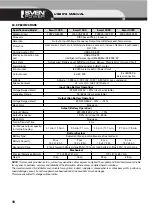
10. SPECIFICATIONS

NOTE:

This manual is provided «as it is», without any warranties, either express or implied. The supplier and its distributors are not liable

for any error, correctness, accuracy and reliability of the information, either express or implied, herein contained.
The manufacturer and its distributor are not liable for any direct, indirect, incidental, consequential, loss of business profits, punitive or
special damages, even if it and its suppliers have been advised of the possibility of such damages.
This manual is subject to changes without notice.

Specifications/Model

Smart 1000

Smart 1500

Smart 2000

Smart 3000

Maximum load

1000 VА/600 W

1500 VА/900 W

2000 VA/1200 W

3000 VA/1800 W

Processor

RISC based micro processor

Detection

Output & Input Voltage, Frequency, Output Load, Battery Level, Temperature

Protection

Over' current, short circuit, latching shutdown, overload, brownout, blackout, input breaker,

RJ 11/45

Communication Port

USB & RS232

Interface connection sup
port

USB & RS232

Intelligent software support Win9X/Me/NT/2000/XP

Indicators

Output Load, Battery Level, AVR Boost & Buck, Bypass, Polarity Error or Ground Fault

Alarm Signal

Audible signals 45 dB at 1 meter

Intput socket

IEC 320 male socket (or Power Cord)

Output socket

6 x IEC 320

6 x IEC 320 &

Screw connection

Altitude

Altitude < 5 000 m, 050°C (32 104°F), 090% RH, non condensing

Agency Approval

UL. cUL, FCC, [CE,TUV] RusТест

Input (Non Battery Operation)

Voltage Range default

220/230/240 V  ± 25% (User's adjustable)

Frequency Range

50/60 Hz (User's adjustable)

Output (Non Battery Operation)

Voltage Range default

220/230/240 V +12% …  14%

Wave Form

Sine wave

Output (Battery Operation)

Output Voltage

220/230/240 V +3% …  10%

Output Frequency

± 0.2% (from Input 50/60 Hz)

Wave Form

Sine wave

Typical Transfer Time

4 ms

Continuous output capacity
for full/half loading

4.1 min./11.3 min.

2.5 min./7.1 min.

4.3 min./11.7 min.

2.7 min./7.9 min.

Battery System

Battery Type

Sealed and leak proof maintenance free lead acid

Battery Capacity

2 pcs 

12 V х 7.2 Аh

2 pcs

12 V х 9 Аh

4 pcs

12 V х 7.2 Аh

4 pcs

12 V х 9 Аh

Recharging Time

4 hours typical (battery voltage 85%), 10 hours max (battery voltage 90%), float change

Mechanical

Physical Dimension WxHxD

173 x 369 x 247 mm

173 x 472 x 247 mm

Weight

15 kg

16 kg

23 kg

26 kg

Summary of Contents for POWER SMART 1000

Page 1: ...smart 1000 1500 2000 3000 POWER SMART 1000 POWER SMART 1500 POWER SMART 2000 POWER SMART 3000...

Page 2: ...SVEN Sven Company Ltd 2007 1 0 V 1 0 http www sven ru 2...

Page 3: ...SMART 1000 1500 2000 3000 1 4 2 4 3 4 4 Smart 4 5 5 6 5 6 1 Smart 5 6 2 Smart 6 7 7 7 1 7 7 2 7 7 3 7 7 4 7 7 5 7 7 6 7 7 7 7 7 8 7 7 9 7 7 10 8 7 11 8 8 8 9 9 10 10 3...

Page 4: ...1 Smart 1000 1500 2000 3000 2 3 1 1 2 1 3 2 4 1 5 RJ 11 1 6 1 7 1 8 1 http www sven ru 4 SMART AVR USB RS 232 DC 4...

Page 5: ...SMART 1000 1500 2000 3000 5 10 15 30 6 6 6 1 Smart a b c d e f g h i Bypass j AVR k AVR l m n o p 5 LOW LINE UPS LOAD LOW LINE UPS LOAD g a o f b n e k j i ha l m b f c d p...

Page 6: ...J 45 b DIP c USB USB USB d DB9 DB9 RS 232 e Reset f g Smart IEC 320 h i j 7 7 1 RS 232 USB Upsilon 2000 6 f g h i j b a d e c FUNCTION 3 2 1 VOLTAGE 220V VOLTAGE 230V VOLTAGE 240V DC START 50Hz DC STA...

Page 7: ...SMART 1000 1500 2000 3000 7 2 c 1 2 220 V 7 3 d 7 4 8 7 5 0 7 0 8 0 7 0 8 0 8 0 7 0 8 0 9 1 0 7 6 7 7 24 24 7 8 1 7 9 3 10 5 7...

Page 8: ...7 10 RJ 11 RJ 45 10 Base T IN OUT 7 11 8 8 5 2 1 3 4 5 6 7 IN O UT...

Page 9: ...SMART 1000 1500 2000 3000 9 9 1 2 3 1 e 2 3 1 2 3 1 2 3 1 2 1 8 2 3...

Page 10: ...00 RISC USB RS 232 Win M NT 2000 XP AVR 45 1 IEC 320 6 IEC 320 6 IEC 320 5000 0 50 C 0 90 UL cUL FCC CE TUV 220 230 240 25 50 60 220 230 240 12 14 220 230 240 3 10 0 2 3 4 4 1 11 3 2 5 7 1 4 3 11 7 2...

Page 11: ...wer System POWER SMART 1000 POWER SMART 1500 POWER SMART 2000 POWER SMART 3000 Please read this operation manual before using the unit and retain this operation manual in safe place for future referen...

Page 12: ...nstallation section in page 13 Technical support http www sven ru TABLE OF CONTENTS 1 Introduction 13 2 Safety Instructions 13 3 Package includes 13 4 The main features 13 5 Storage 13 6 Controls and...

Page 13: ...e UPS power cord in any area where it may get damaged by heavy objects Do not connect UPS to home appliance e g hairdryer fan etc Do not connect UPS to Laser printer If you store the UPS or UPS does n...

Page 14: ...onnection b DIP Switch The voltage frequency of the UPS might be re set by the DIP Switch on the rear panel of the UPS The following charts may bring you clear pictures about how the settings are done...

Page 15: ...to the wall receptacle 7 3 Turn Off the UPS Push the Off Switch for at least 3 seconds to turn off the UPS If you press the Off Switch less than 3 seconds the UPS will not execute shutdown command du...

Page 16: ...n the Battery Replacement LED Red lights up you may leave the UPS to be re charged for at least 8 10 hours to see whether the Red LED will be extinguished after the Self test Function is executed agai...

Page 17: ...tatus if it is in over load Remove some uncritical load Alarm buzzer beeps for 10 seconds then the UPS is turned off Remove some uncritical load and re switch on the UPS No LED s display on the front...

Page 18: ...are support Win9X Me NT 2000 XP Indicators Output Load Battery Level AVR Boost Buck Bypass Polarity Error or Ground Fault Alarm Signal Audible signals 45 dB at 1 meter Intput socket IEC 320 male socke...

Page 19: ...Eng SMART 1000 1500 2000 3000 19...

Page 20: ......

Reviews: