2
SVERO Trolleys -20, -21, -24
Read this manual before mounting
the trolley and its use. Incorrect handling may cause danger!
Description
Svero trolleys are to be mounted to I-beams for carrying loads, which can be moved along the
beam. In the trolley a lifting device is to be hanged. It can be manually, electric or pneumatically
driven. Svero trolleys are adjustable within certain width ranges. The trolleys can be used for I-
beams with plane flanges (such as IPE, HEA or HEB types) or beams with sloping flanges (such as
INP-beams). The possible width ranges are shown in the data tables. The suspension bolt has got
a right- and a left-handed thread for easy mounting to the side plates. The suspension bolt is
turned down in its centre part where the hook of the lifting device has to be placed. Thereby the
suspension bolt will not rotate.
The trolley models -20 and -24 are to be pushed only but the -21 models are driven by means of a
hand chain. All trolleys are manufactured with a protection against falling (in case of wheel brake
down) and climbing protection (so that the wheels cannot climb to the top of the beam flange).
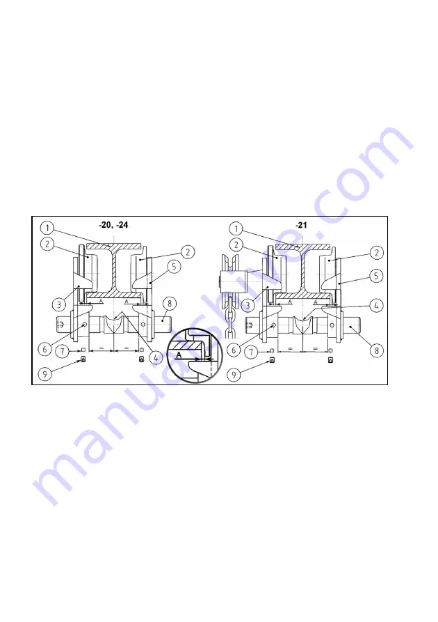
Fig 1 Trolleys mounted to an I-beam (H-beam)
Mounting (
fig 1)
The end of the suspension bolt (8) with a tiny hexagon hole is right hand threaded. Screw it by
hand about 5 mm into the right threaded hole of the side plate (3), which is marked “H”. After that
the other side plate (5) has to be screwed about 5 mm onto the other end of the suspension bolt.
Note that here the threads are left threaded. Now the trolley can be hanged up to the I-beam (1) so
that the trolley wheels will be placed on the lower flange of the beam. By means of the included
hexagon key rotate the suspension bolt and adjust the distance between the side plates. A certain
space between wheel flange and beam flange is important. Measure
A
at each side of the actual
trolley must be:
0,5 – 1 ton
measure A = 1 – 1,5 mm
2 – 3 ton
measure A = 1,5 – 2 mm
5 ton
measure A = 2 – 2,5 mm
Adjust the suspension bolt so that the position (4) for the lifting device hook is upwards. Check that
measure A as per above still is kept.
The two soft plugs (7), included in the delivery, should be put into the holes (6). The stop screws
(9) are to be screwed into the holes (6) and tightened so that the suspension bolt has been locked.


