3
Make sure that the distance to the nearest pulley is sufficiently large so that the rope cannot
mount the drum flange. The line must be wound evenly on to the drum.
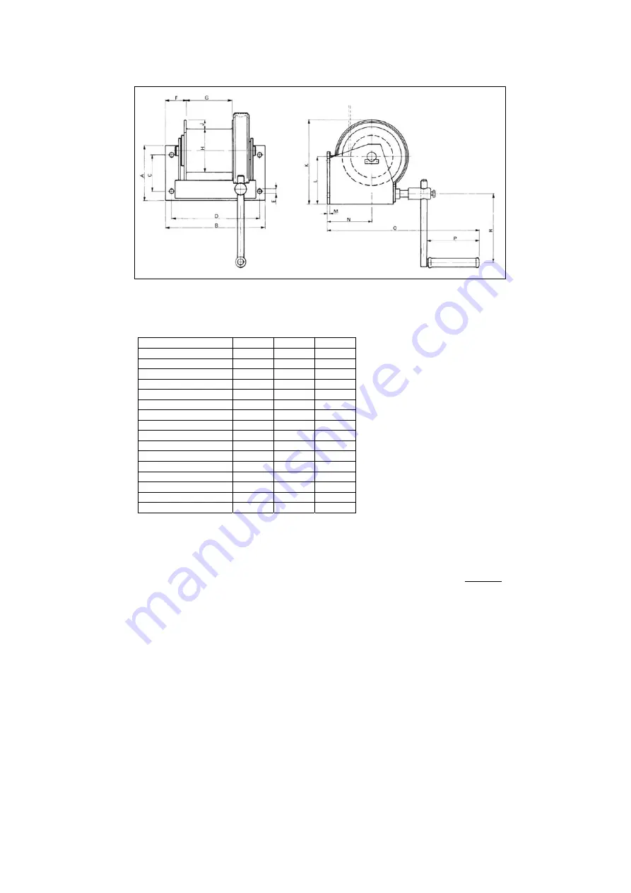
Fig. 2 Dimensioned sketch
Dimensions table
Model
6211A
6113A
6114A
Dimension A mm
157 180 180
Dimension B mm
210 320 350
Dimension C mm
100 120 120
Dimension D mm
183 280 320
Dimension E dia. mm
14 17 17
Dimension F mm
45 63 63
Dimension G mm
71 150 170
Dimension H dia. mm
100 140 140
Dimension J mm
28 28 52
Dimension K mm
225 285 332
Dimension L mm
132 164 189
Dimension M mm
4 8 10
Dimension N mm
115 150 177
Dimension O mm
350 463 540
Dimension P mm
105 145 145
Dimension R max mm
225 360 360
Function testing
Attach a load (up to maximum load) and raise approx. 0.5 m by turning the crank clockwise. Check
that the load is held where it is by the brake without letting go of the crank. Then lower the load in
stages without fully letting go of the crank. Then check the functions, raising, lowering and load
holding (releasing the crank). When the crank is released it may rotate backwards by maximum a
half turn. The brake must then hold the load without slipping.
Summary of Contents for 6113A
Page 5: ...5 Appendix Spare parts drawing with lubricating points NB 2009 03 08 ...
Page 10: ...10 Bilaga Reservdelsritning med smörjställen NB 2009 03 08 ...
Page 15: ...15 Vedlegg Oversikt over reservedeler med smørepunkter NB 2009 03 08 ...
Page 20: ...20 Liite Varaosapiirros voitelukohtineen NB 08 03 09 ...


