background image

10278L

SW-Stahl GmbH

BE

D

IE

N

UN

G

S

A

N

L

E

IT

UN

G

29

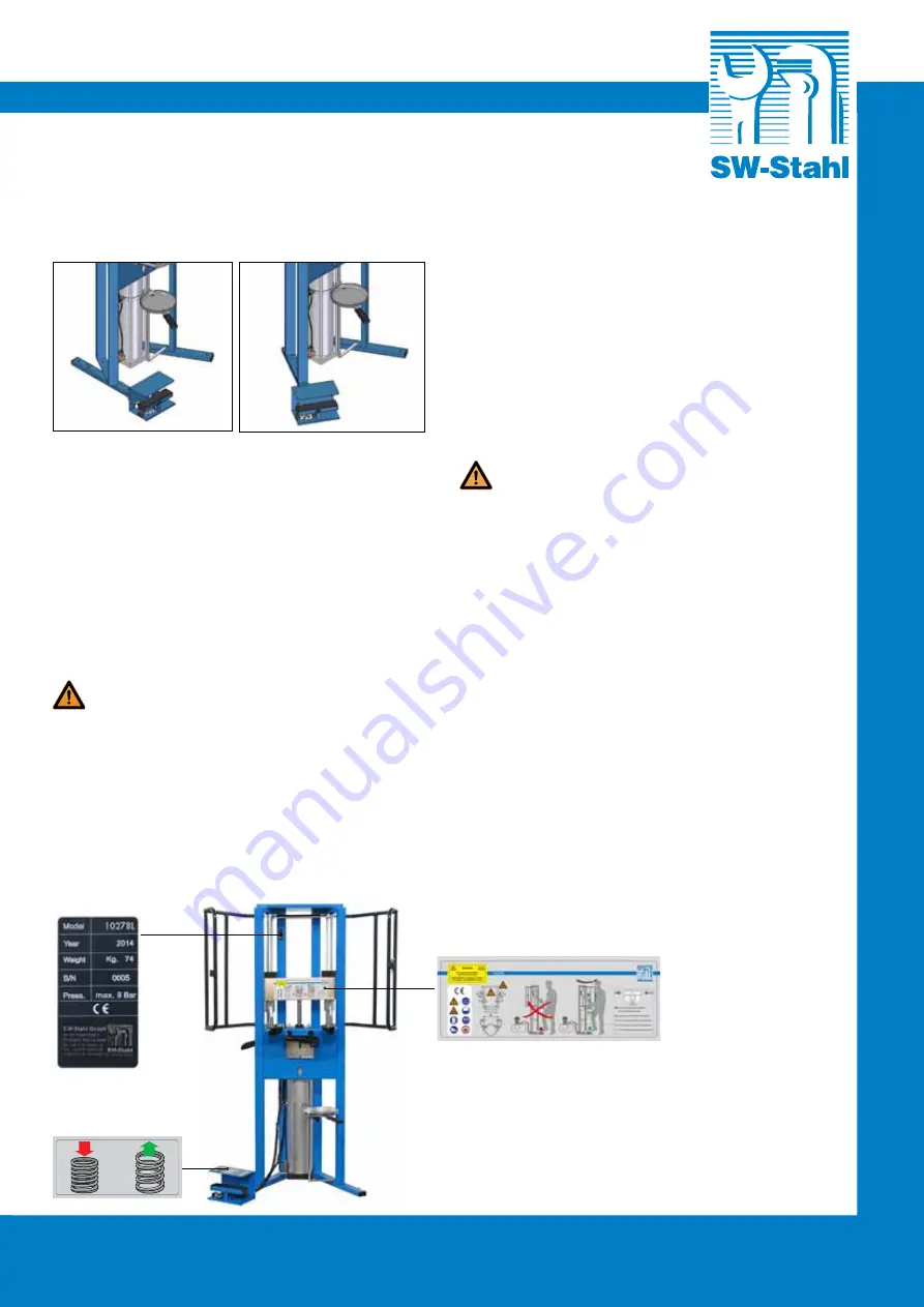
Fije el pie con pedal en el bastidor, tal como se describe 

a continuación:

Antes 

Después

Se recomienda no dejar partes del embalaje al 

alcance de los niños. Eliminar el embalaje en un lugar 

autorizado.

7.  UBICACIÓN E INSTALACIÓN

La máquina 10278L puede ponerse en el lugar más 

cómodo y mejor para el operador ya que no plantea 

exigencias particulares a excepción de la conexión 

con el suministro de aire comprimido. Se recomienda 

utilizar la máquina en entornos que dispongan de una 

iluminación mínima de 600 lux.

  Es  obligatorio  fijar  la  máquina  al  suelo, 

utilizando  los  cuatro  orificios  presentes  en 

los pies inferiores.

8. CONEXIONES

La máquina se ha de conectar a una red de suministro 

de aire comprimido. Comprobar que la presión de la red 

de suministro de aire comprimido se encuentre entre 

5 y 8 bar. Si la presión es mayor, utilizar dispositivos 

adecuados (por ejemplo, un reductor de presión) para 

reducirla.

9. CONTROLES

Controlar  la  eficiencia  de  la  conexión  del  aire,  para 

ello  verificar  que  los  valores  del  suministro  del  aire 

comprimido estén comprimidos entre 5 y 8 bar. 

Comprobar que los empalmes y/o los elementos 

neumáticos no tengan pérdidas (si las hay, ponerse 

en contacto con el distribuidor). Verifique el correcto 

el funcionamiento de la válvula de entrada: con la 

protección abierta, la máquina no debe funcionar.

10. 

PUESTA EN FUNCIONAMIENTO Y 

UTILIZACIÓN

  NO LUBRICAR NUNCA con grasa y aceite las 

comumnas de deslizamiento.


Cada 200 ciclos de trabajo y sin embargo cada 60 

días eliminar el sucio y el pulvo sobre las columnas de 

deslizamiento. Tras haber realizado las operaciones de 

ensamblaje y de conexión, la máquina puede empezar 

a funcionar. La máquina se entrega con la barra 

completamente levantada. Accionar el pedal de mando 

para bajar la barra y poner la máquina en el modo de 

funcionamiento. Colocar la horquilla adecuada para el 

amortiguador que se quiere desmontar para la primera 

operación.

10.1 Desmontaje

Consultar siempre las instrucciones de servicio 

del fabricante o el manual correspondiente para 

establecer los procedimientos y los datos corrientes. La 

información sobre el producto establece los datos de las 

aplicaciones y el uso de las herramientas a mero título 

informativo. Para facilitar el desmontaje, se aconseja 

desbloquear las tuercas que bloquean los capuchones 

de los amortiguadores antes de colocarlos en la 

máquina 10278L. Algunos fabricantes de automóviles 

indican el desbloqueo de las tuercas de bloqueo en 

Summary of Contents for 10278L

Page 1: ...ahrzeuge GB Pneumatic coil spring compressor extra heavy duty for passengers cars suv armour plated and commercial vehicles F D monte amortisseurs pneumatique extra puissant pour v hicules SUV v hicul...

Page 2: ...10278L SW Stahl GmbH An der Hasenjagd 3 D 42897 Remscheid Tel 49 0 2191 46438 0 Fax 49 0 2191 46438 40 E Mail info swstahl de 2...

Page 3: ...7 AUFSTELLUNG UND INSTALLATION 5 8 ANSCHL SSE 5 9 KONTROLLEN 5 10 INBETRIEBNAHME UND BENUTZUNG 5 10 1 Ausbau 5 10 2 Einbau 6 11 ST RUNGEN URSACHEN ABHILFEN 6 12 VORSICHTSMASSNAHMEN BEI L NGERER NICHTB...

Page 4: ...rwerkfeder eine potentielle Gefahrenquelle darstellen Die Gefahr ist durch die Kraft der Federspannung gegeben Das Ger t darf nur mit richtig montiertem Schutzk fig eingesetzt werden 4 1 Individuelle...

Page 5: ...nerhalb der vorgegebenen Werte von 5 bis 8 bar liegt Die Druckluftanschl sse und die pneumatischen Bauteile auf eventuelle Leckagen kontrollieren wenden Sie sich ggf an den Fachh ndler Die Funktionst...

Page 6: ...n Sie einige Tropfen Druckluftwartungr l in den Auschlussnippel ein Schlie en Sie nun Den Sto d mpfer mit der ersten Federwindung auf der unteren Federaufnahme positionieren Abb 1 den Sto d mpfer dreh...

Page 7: ...schlie end die oberen Spannbacken auf der ersten benutzbare Federwindung ansetzen Nach der genauen Positionierung der oberen Spannbacken sind die schwenkbaren Arme Abb 4 durch Anziehen der Arretierheb...

Page 8: ...beh r schlechter Qualit t oder von ungeeignetem Zubeh r Bei Gew hrleistungsantr gen sind vorzulegen das Ger t mit der betreffenden Seriennummer und die lesbare Originalrechnung ohne Streichungen mit d...

Page 9: ...AND INSTALLATION 11 8 CONNECTIONS 11 9 CONTROLS 11 10 FUNCTIONING AND USAGE 11 10 1 Disassembling 11 10 2 Assembling 12 11 OPERATION ANOMALIES CAUSES SOLUTIONS 12 12 MACHINE IDLED FOR A LONG PERIOD 12...

Page 10: ...d springs can be potential dangers due to force collected because of compression This machine must be used always with its specific frontal protection mounted correctly on the frame 4 1 Individual pro...

Page 11: ...Check the working efficiency of the inlet valve the machine should not work when the guard is open 10 FUNCTIONING AND USAGE NEVER LUBRICATE the sliding parts columns with GREASES or OILS Every 200 wo...

Page 12: ...bracket in the first coil fig 1 rotate the shock absorber and lock it in the bracket in the maximum slipping point fig 2 Put the small arms near the spring and insert the upper vices in the first coi...

Page 13: ...shock absorber inside the vice in order to center it on the machine see fig 5 Put the small arms near the spring and insert the upper vices in the first coil available After having found the right po...

Page 14: ...modified or featuring traces of shock use with poor quality or non compatible accessories To use the guarantee provide the tool with its serial number as well as the legible and unmarked original invo...

Page 15: ...ALLAGE 16 7 EMPLACEMENT et INSTALLATION 17 8 BRANCHEMENTS 17 9 CONTR LES 17 10 MISE EN MARCHE ET UTILISATION 17 10 1 D montage 17 10 2 Remontage 18 11 DYSFONCTIONNEMENTS CAUSES REM DES 18 12 INUTILISA...

Page 16: ...ts comprim s repr sentent un danger potentiel Le danger est d termin par la force exerc e par effet de ladite compression L appareil doit toujours tre utilis avec la structure de protection mont e cor...

Page 17: ...e r f rer aux instructions du constructeur du v hicule ou au manuel du v hicule pour conna tre les donn es et les proc dures en vigueur utiliser Cette fiche d information produit montre les applicatio...

Page 18: ...l trier inf rieur dans la premi re spire fig 1 faire tourner l amortisseur jusqu au point o l trier s encastre au point maximum de coulissement fig 2 Approcher les bras orientables du ressort puis in...

Page 19: ...ositionner l amortisseur en serrant fortement la tige l int rieur de l tau de mani re ce que l amortisseur r sulte centr sur la machine fig 5 Approcher les bras orientables du ressort puis ins rer les...

Page 20: ...de chocs utilisation avec accessoires de mauvaise qualit ou non compatibles Pour utiliser la garantie pr senter l outil avec le num ro de s rie correspondant ainsi que la facture originale lisible et...

Page 21: ...COLLOCAZIONE e INSTALLAZIONE 23 8 COLLEGAMENTI 23 9 CONTROLLI 23 10 MESSA IN FUNZIONE E UTILIZZO 23 10 1 Smontaggio 23 10 2 Rimontaggio 24 11 MALFUNZIONAMENTI CAUSE RIMEDI 24 12 ACCANTONAMENTO PER LU...

Page 22: ...ituiscono un potenziale pericolo Il pericolo determinato dalla forza imbrigliata per effetto della compressione stessa Il prodotto va sempre utilizzato con la struttura di protezione montata correttam...

Page 23: ...denti d aria dai raccordi e o elementi pneumatici in tal caso rivolgersi al rivenditore Controllare il corretto funzionamento della valvola di ingresso con protezione aperta la macchina non deve funzi...

Page 24: ...ella prima spira fig 1 far ruotare l ammortizzatore fino al punto in cui la staffa si incastra nel punto massimo di scorrimento fig 2 Avvicinare i braccetti orientabili alla molla e successivamente in...

Page 25: ...ccessivamente inserire i morsetti superiori sulla prima spirale utile Dopo aver trovato il giusto posizionamento della molla sulla staffa e aver posizionato i morsetti superiori bloccare i braccetti o...

Page 26: ...numero di serie nonch la fattura originale leggibile e senza cancellature riportante la designazione del prodotto e la data d acquisto Condizioni dettagliate di applicazione della garanzia rivolgersi...

Page 27: ...EXIONES 29 9 CONTROLES 29 10 PUESTA EN FUNCIONAMIENTO Y UTILIZACI N 29 10 1 Desmontaje 29 10 2 Montaje 30 11 PROBLEMAS DE FUNCIONAMIENTO CAUSAS Y SOLUCIONES 30 12 ALMACENAJE DURANTE PERIODOS PROLONGAD...

Page 28: ...lo 10278L ya que los muelles comprimidos constituyen un potencial peligro El peligro es determinado por la fuerza sujetada por efecto de la misma compresi n El producto ha de utilizarse siempre con la...

Page 29: ...y o los elementos neum ticos no tengan p rdidas si las hay ponerse en contacto con el distribuidor Verifique el correcto el funcionamiento de la v lvula de entrada con la protecci n abierta la m quina...

Page 30: ...inferior en la primera espiral fig 1 y hacer girar el amortiguador hasta que la horquilla encaje en el punto m ximo de deslizamiento fig 2 Acercar los brazos orientables al muelle y posteriormente co...

Page 31: ...o de banco para colocar el amortiguador y centrarlo en la m quina fig 5 Acercar los brazos orientables al muelle y posteriormente colocar las mordazas superiores sobre la primera espiral til Tras habe...

Page 32: ...ubiertos por la garant a legal Dicha garant a no es aplicable en los siguientes casos desgaste normal incumplimiento de las instrucciones de uso y de las prescripciones de seguridad uso no convenciona...

Page 33: ...10278L SW Stahl GmbH BEDI ENUNGSA NLEITUNG 33...

Page 34: ...02000 4 16 321000002 1 17 832002000 2 18 821011000 2 19 815001000 4 20 321000046 2 21 824001000 12 22 321000026 2 23 321042011 1 24 321000008 2 25 871001000 2 26 836001000 2 27 822015000 2 28 32109400...

Page 35: ...10278L SW Stahl GmbH BEDI ENUNGSA NLEITUNG 35 46 16 3 24 22 19 18 52 21 17 25 47 28 1 51 23 27 26 37 38 40 41 39 1 30 54 53 42 43 55...

Page 36: ...10278L SW Stahl GmbH An der Hasenjagd 3 D 42897 Remscheid Tel 49 0 2191 46438 0 Fax 49 0 2191 46438 40 E Mail info swstahl de 36...

Page 37: ...siehe Typenschild in die untenstehende Tabelle zu bertragen MASCHINEN TAGEBUCH Empfohlene Wartungsarbeiten F hrungss ulen im Abstand von 2 Monaten oder nach 200 Betriebsabl ufen mit einem trockenen T...

Page 38: ...ie Serien Nummer und das Baujahr siehe Typenschild in die untenstehende Tabelle zu bertragen MASCHINEN TAGEBUCH Empfohlene Wartungsarbeiten F hrungss ulen im Abstand von 2 Monaten oder nach 200 Betrie...

Page 39: ...10278L SW Stahl GmbH BEDI ENUNGSA NLEITUNG 39...

Page 40: ...SW Stahl GmbH An der Hasenjagd 3 D 42897 Remscheid Tel 49 0 2191 46438 0 Fax 49 0 2191 46438 40 E Mail info swstahl de...

Reviews: