background image

3

3 0 1 0 5 1 L

S I C H E R H E I T S H I N W E I S E


Immer Fahrzeugherstellerangaben beachten!


Verwenden Sie immer eine fahrzeugspezifische Servieliteratur, dieser können Sie wichtige  
Hinweise wie Dremomentwerte und zusätzlicher Informationen für die Demontage und  
Montage des Radlagers entnehmen.


Bei der Montage der Lager-Nabeneinheit muss ein Klickgeräusch zu hören sein. Das Klickge-
räusch zeigt an, dass die Blech-Haltekrallen der Naben-Lagereinheit in die Haltenut des Rad-
lagergehäuses springen. Wird die Naben-Lagereinheit nicht ordnungsgemäß montiert, besteht 
die Gefahr, dass das Lager keinen festen Halt im Radlagergehäuse hat. Dies kann zu Unfällen mit 
schweren Verletzungen und Sachschäden führen.

A N W E N D U N G
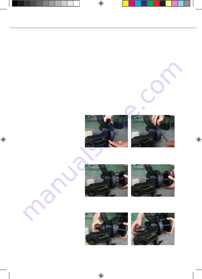
A LT E   L AG E R E I N H E I T  D E M O N T I E R E N

Demontageschalen (4) am
Radlagergehäuse montieren.
Diese werden mit zwei
Innensechskant-Schrauben (9)
verbunden.

Druckstifte (3) vorsichtig mit einem
Hammer in die Druckplatte
einschlagen, dabei müssen
Druckstifte (3) auf dem gleichen
Lochkreis der Radnabe liegen.
Spindel (1) mit aufgesetzter
Druckplatte (2) von vorne aufsetzen,
so dass die montierten Druckstifte
(3) durch die Radbolzen-Bohrungen
an der Demontageschalen (4)
anliegen.

Demontage-Druckplatte (7)
antriebswellenseitig auf die Spindel
stecken und mit der Spindelmutter
(8) alle Bauteile von Hand
vorspannen. 

301051L_manual_75600_en_de_roh.indd   3

301051L_manual_75600_en_de_roh.indd   3

10.11.20   17:52

10.11.20   17:52

Summary of Contents for 301051L

Page 1: ...301051L BEDIENUNGSANLEITUNG KOM PAK TLAGER WERKZEUGSATZ 301051L_manual_75600_en_de_roh indd 1 301051L_manual_75600_en_de_roh indd 1 10 11 20 17 52 10 11 20 17 52 ...

Page 2: ...Inkl Spindel und Drucklager für mechanische Betätigung INHALT 1 Hochfeste kugelgelagerte Spindel 2 Druckplatte mit 8 Nebenbohrungen 3 5 Druckstifte 4 Demontageschalen 5 Montageschale 6 Montage Druckplatte 7 Demontage 8 Spindelmutter 9 Befestigungsschrauben für Schalen 301051L_manual_75600_en_de_roh indd 2 301051L_manual_75600_en_de_roh indd 2 10 11 20 17 52 10 11 20 17 52 ...

Page 3: ... im Radlagergehäuse hat Dies kann zu Unfällen mit schwerenVerletzungen und Sachschäden führen ANWENDUNG ALTE LAGEREINHEIT DEMONTIEREN Demontageschalen 4 am Radlagergehäuse montieren Diese werden mit zwei Innensechskant Schrauben 9 verbunden Druckstifte 3 vorsichtig mit einem Hammer in die Druckplatte einschlagen dabei müssen Druckstifte 3 auf dem gleichen Lochkreis der Radnabe liegen Spindel 1 mit...

Page 4: ...ageschalen 5 mit den Schrauben 9 an der neuen Naben Lagereinheit befestigen Die neue Naben Lagereinheit auf die Druckplatte 2 legen so dass dievormontierten Druckstifte 3 durch die Bohrungen in der Radnabe auf den Montageschalen 5 aufliegen Das Montage Druckstück 6 antriebswellenseitig anhalten und Spindel 1 mit aufgesetzter Druckplatte 2 und neuer Naben Lagereinheitvonvorne durch das Schwenklager...

Page 5: ...5 301051L 5 INSTRUCTION MANUAL COM PAC T BEARING TOOL SET 301051L 301051L_manual_75600_en_de_roh indd 5 301051L_manual_75600_en_de_roh indd 5 10 11 20 17 52 10 11 20 17 52 ...

Page 6: ...nd pressure units for mechanical operation CONTENT 1 High strength ball bearing spindle 2 Mounting plate with 8 holes 3 5 bolts 4 Dismounting shells 5 Mounting shells 6 Mounting plate 7 Dismounting plate 8 Spindle nut 9 Fastening bolts for mounting shells 301051L_manual_75600_en_de_roh indd 6 301051L_manual_75600_en_de_roh indd 6 10 11 20 17 52 10 11 20 17 52 ...

Page 7: ...s that the bearing has no firm hold in the wheel bearing housing This can lead to accident serious injury and property damage INSTRUCTION DISASSEMBLING Mount the dismantling shells 4 on the wheel bearing housing with two screws 9 Hammerthe bolts 3 carefully into the mounting plate the bolts 3 have to be aligned with the wheel hub s hole circle During the disassembly the bolts press against the mou...

Page 8: ...ing shells 9 Laythe new hub bearing unit onto the mounting plate 2 so that the pre assembled bolts 3 touch the mounting shells 5 through the wheel stud holes Attach the mounting plate 6 sideways to the drive shaft and lead the spindle 1 with the attached mounting plate 2 and new hub bearing unit from the front through the swivel bearing and the mounting plate 6 Pull in the newwheel bearing with th...

Page 9: ...9 301051L NOTIZEN 301051L_manual_75600_en_de_roh indd 9 301051L_manual_75600_en_de_roh indd 9 10 11 20 17 52 10 11 20 17 52 ...

Page 10: ...10 NOTIZEN 301051L_manual_75600_en_de_roh indd 10 301051L_manual_75600_en_de_roh indd 10 10 11 20 17 52 10 11 20 17 52 ...

Page 11: ...11 301051L NOTIZEN 301051L_manual_75600_en_de_roh indd 11 301051L_manual_75600_en_de_roh indd 11 10 11 20 17 52 10 11 20 17 52 ...

Page 12: ... 464380 Fax 49 2191 4643840 SW STAHL GMBH An der Hasenjagd 3 D 42897 Remscheid www swstahl de info swstahl de 301051L_manual_75600_en_de_roh indd 12 301051L_manual_75600_en_de_roh indd 12 10 11 20 17 52 10 11 20 17 52 ...

Reviews: