


6
Section II
Assembly Procedures for
Swagelok 7N, 7P, 7R, and 8R
Thermoplastic Hose using the
Power Swager
Pre-Assembly
1.
Be sure the hose and all components are in good condition.
Note: The lead end of the hose should be cut squarely.
2.
Verify that the swager is in proper working order as outlined
in Section I.
Cutting Bulk Hose
1.
Determine the desired hose and end connection size and
type.
2.
Determine the desired hose assembly overall length.
3.
See the
End Connections and Pushers chart on page 8 to
determine the fitting cut-off length.
4.
Subtract the desired fitting cut-off lengths from each end of
the hose assembly overall length. Note: The result is the
overall cut length.
5.
Measure and mark the hose at the overall cut length.
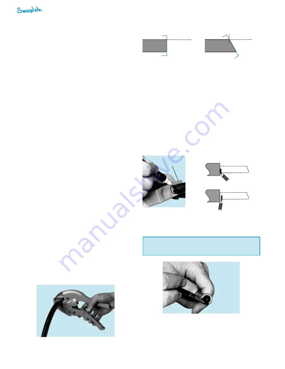
6.
Cut the hose squarely at the mark.
Improper Cut
Proper Cut
Hose Axis
Hose Axis
Cut Plane
Cut Plane
Cut Plane
Cut Plane
Cut is not square and
perpendicular with hose axis.
Cut is square and
perpendicular with hose axis.
Alignment of Dies in the Swager Die Bowl
The dies are aligned at the factory. However, if at any time the
dies are not of equal height when seated in the die bowl, they
must be readjusted. To readjust the dies:
1.
Loosen the four (4) mounting bolts on the die lifting fingers.
2.
Push each die lifting finger assembly down as far as the bolt
holes will allow.
3.
Turn on the swager.
4.
Pull the valve handle until the pusher bottoms on the dies,
leaving the pusher in contact with the dies.
5.
Retighten the bolts.
Adjustment of Eccentric Guide Bushings
This adjustment is made at the factory. However, the eccentric
guide bushings may be readjusted if the dies are catching on
the top edge of the frame. To adjust:
1.
Place the swager in the full downward position.
2.
Locate the eccentric guide bushings on the lower outside
bars of the frame.
3.
Loosen the mounting bolts.
4.
Rotate the bushings counter-clockwise to tighten.
Note: The die lifting arms must slide freely.
End Connection Preparation
Remove all plastic caps, plugs, nuts, and ferrules prior to
swaging an end connection.
Proper Mark Position
Improper Mark Position
Inserting End Connections
1.
Mark each hose end with the correct insertion depth.
2.
Use the appropriate depth insertion gage:
■
MS-IGB-1 for 1/4, 3/8, and 1/2 in. hose.
■
MS-IGB-2 for 3/4 and 1 in. hose.
3.
Insert hose until it bottoms out.
4.
Mark the hose. Note: The bottom of the mark should line up
with the top of the insertion gage.
depth insertion
gage
5.
If acceptable for the application, apply a thin coat of clean,
SAE 20 weight lubricating oil to approximately the first 1/2 in.
(12 mm) depth of the hose ID.
!
Caution!
Never use oil in 7P (poly pure) hose.
Power Swager
Summary of Contents for MS-PSR-110
Page 11: ...Power Swager 11 ...


