– 7 –
Assembling Components
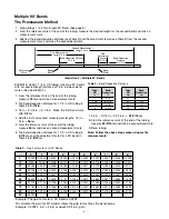
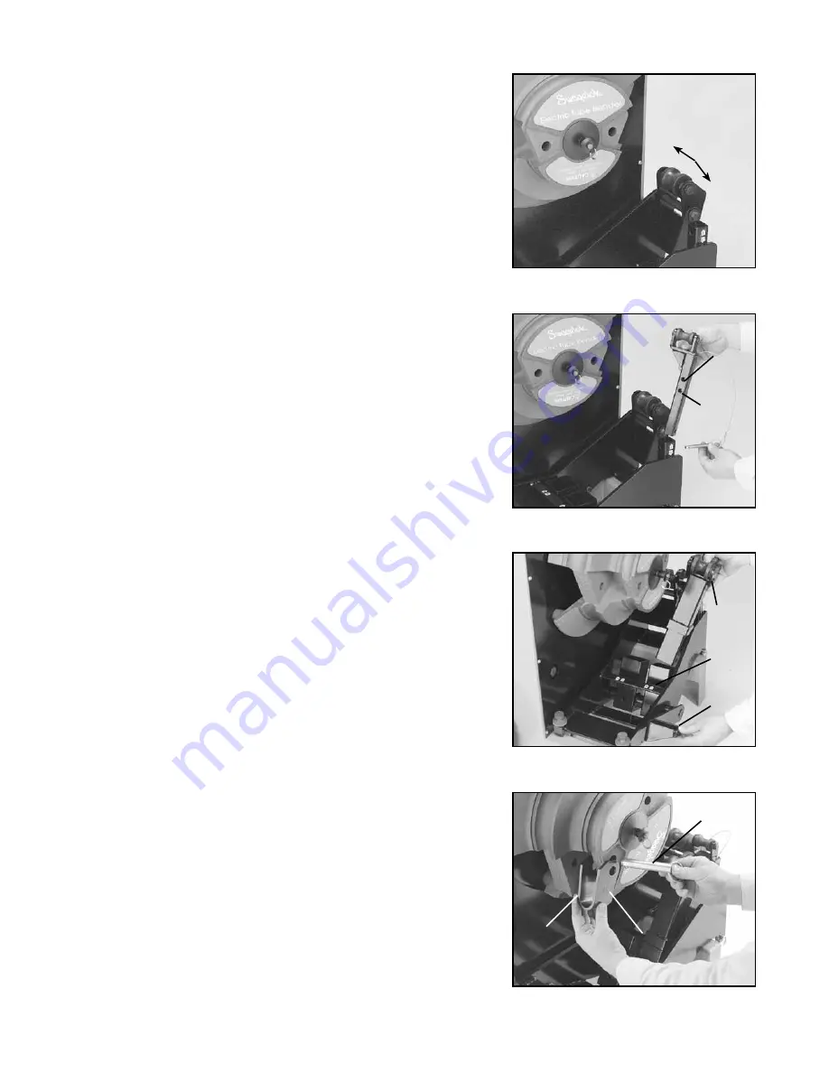
1. Select and install proper tail rollers. To bend 1 1/2 in. (38 mm) OD
tubing, use the fixed tail roller in the up position. For 2 in. (50 mm) OD
tubing, use the fixed tail roller in the down position. (See Figure 1.)
To bend 1 in. (25 mm) OD tubing, use the 1 in. (25 mm) removable tail
roller, securing pin in lower pin hole (up position). For 1 1/4 in. (32
mm) OD tubing, use the 1 1/4 in. (32 mm) removable tail roller, securing
pin in upper pin hole. Align roller with the inside of the unit. (See Figure
2.)
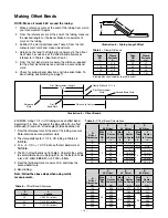
2. Select proper roller tower; the size is indicated on roller tower. To install,
lift and hold the handle lock. Insert the roller tower into proper bridge
opening so that the size indicator faces you. Allow roller tower to lean
against tail roller. (See Figure 3.)
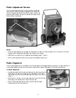
3. Select proper tube clamp; the size is indicated on clamp face. Locate
the tube size on the bend shoe, and attach the tube clamp with pin,
making sure the size identification faces out. (See Figure 4.)
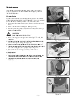
4. Make sure the circuit breaker is switched to the ON position and the
EMERGENCY STOP button is not engaged.
5. Plug the unit into an appropriate power source. The display on the
pendant will illuminate.
Figure 4
Pin
Tube
Clamp
Size
Indicator
Figure 2
Upper
Pin Hole
1 1/4 in.
(32 mm)
Lower
Pin Hole
1 in.
(25 mm)
Figure 3
Roller
Tower
Size
Indicator
Roller
Tower
Label
Location
Handle
Lock
Figure 1
Up Position
1 1/2 in.
(38 mm)
Down
Position
2 in.
(50 mm)
Summary of Contents for MS-TBE-1 series
Page 1: ...Electric Tube Bender User s Manual www swagelok com ...
Page 15: ... 15 ...

