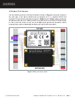
Pin Number
Name
Type
Description
1,3,5-8,10,12,
14,16,19-20,
22-25,28,30-33,
36,38,44-49, 51
NC
NC
No Connection
2,39,41,52
VDD
Power
3.3V/5V
at
up
to
1000mA/600mA
4,9,15,18,21,26,
27,29,34,35,37,
40,43,50
GND
Ground
Ground
11
UART_RX
Comms
3.3V serial receive
13
UART_TX
Comms
3.3V serial transmit
17
T/R
OUTPUT
Digital Output
Transmit/Receive indicator
*leave unconnected if not
used
42
GPIO1
Digital Output/Analog
Input
General
purpose
input/output
Table 6:
Modem pin numbers and descriptions.
Additional Notes
Pin Number
Note
42
Connection is unbuffered and connected directly to a GPIO on the Modem
processor. Configuration will be provided via serial commands. GPIO1 pin
is 3.3V tolerant and open drain, with a sink current limit of 8 mA (20 mA
with a relaxed VOL/VOH)
2, 39, 41, 52
The VDD connection points are in parallel with one another and power the
Modem. If the designer wants to enable a complete power off mode, a load
switch can be provided here
17
HIGH when transmitting
LOW when receiving
The state will not change faster than 500μs prior to the Modem beginning
to transmit and 500μs after the Modem has finished transmitting.
*leave open if not used
Table 7:
Additional notes on pin numbers.
© 2022 SWARM TECHNOLOGIES
SWARM M138 MODEM PRODUCT MANUAL · REV 1.20 · FEBRUARY 2022
PAGE
15


