background image

SECTION 5– SETTING THE KNIFE GAP 

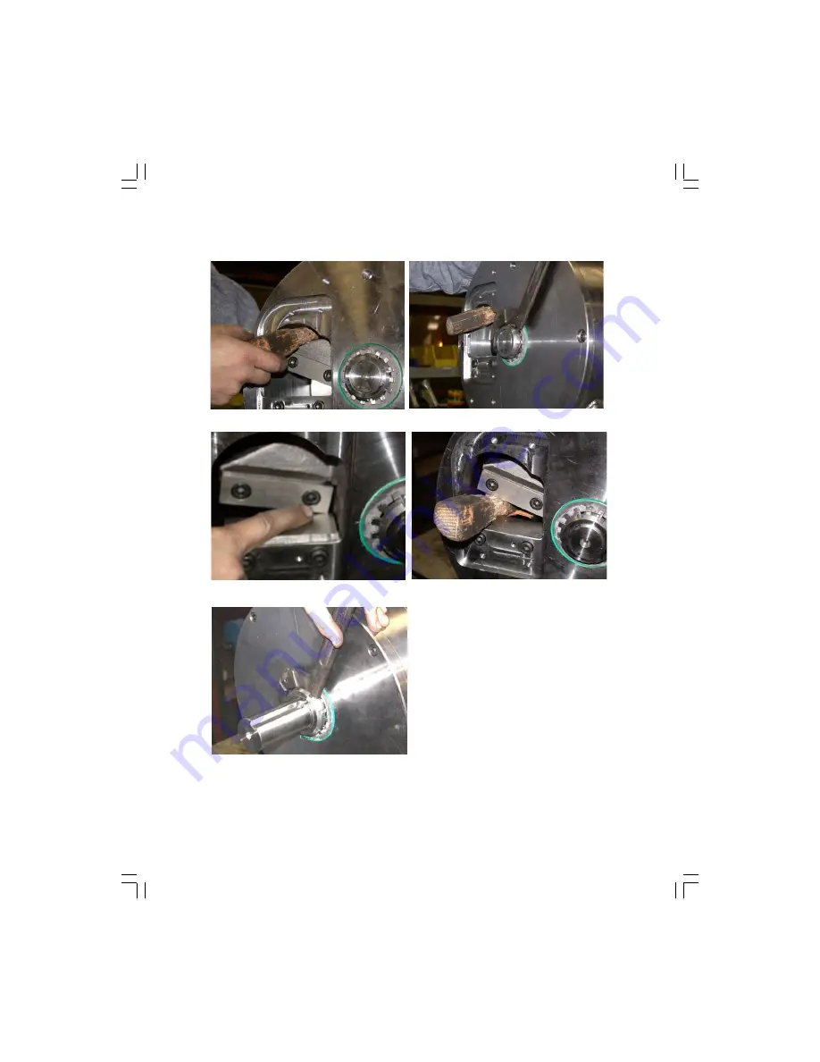
Figure 5-1:  Lock rotating holder in place from top.          Figure 5-2: Tighten front lock nut first. 

   Figure 5-3: Tighten until knives make contact.          Figure 5-4: Lock holder in place from bottom. 


5.1 – SETTING THE KNIFE GAP 

Wedge a piece of wood (or similar) between the ro-
tating holder and housing to keep it from spinning 
while tightening the front lock nut. MAKE SURE THE 
REAR LOCK NUT IS LOOSE – this will allow the knife 
holder to move forward toward the stationary knife 
as the front lock nut is tightened.  Use Span-A-
Wrench or similar tool to tighten the front lock nut. 
Tighten until the knives make contact, as shown in 
Figure 5-3. 


Figure 5-5:  Tighten rear lock nut. 
 
Lock the rotating knife holder in the opposite direction, as shown in Figure 5-4. Tighten the rear lock 
nut. Apply an initial torque of approximately 100 lb-ft to the rear lock nut to pull the rotating knife away 
from the stationary knife.   

Summary of Contents for 510AF-AH

Page 1: ...NAGEABLE SCRAP INTO MANAGEABLE ASSETS REPAIR MANUAL SCRAP CHOPPER MODEL 510AF AH MANUFACTURED BY SWEED MACHINERY P O BOX 228 GOLD HILL OREGON 97525 PHONE NO TOLL FREE 1 800 888 1352 1 541 855 1512 FAX...

Page 2: ...TION 6 2 3 ROTATING KNIFE INSTALLATION 7 3 FRONT AND REAR PLATE INSTALLATION 8 3 1 INSTALLING THE FACE PLATE 8 3 2 INSTALLING THE STATIONARY KNIFE 8 3 3 INSTALLING THE ROTATING KNIFE HOLDER REAR PLATE...

Page 3: ...t the inside shoulder of the plate bore Failure to seat the race against the shoulder at this step will result in knife gap problems during final assembly NOTE Earlier models use a face plate that has...

Page 4: ...cont 1 3 STATIONARY KNIFE SHIM INSTALLATION Clean the knife pocket prior to installing the shim to ensure proper seating of the shim Figure 1 6 Face Plate Knife Shim Figure 1 7 Installing shim CB00813...

Page 5: ...shoulder of the plate bore Failure to seat the race against the shoulder at this step will result in knife gap problems during final assembly NOTE Earlier models use a rear plate that has a retaining...

Page 6: ...necessary to provide clearance between the key and machined radius of the shaft keyway NOTE Always use an anti seize lubricating compound such as E Z Break prior to pressing the holder onto the shaft...

Page 7: ...8 Seat knife using a brass mallet 2 3 ROTATING KNIFE INSTALLATION Clean the knife pocket prior to installing the knife to ensure proper seating of the knife Torque knife bolts to 50 lb ft Tap knife w...

Page 8: ...the face plate with the housing bore and tap into place Torque the 3 8 16 button head screws to 45 lb ft 3 2 INSTALLING STATIONARY KNIFE Clean the knife pocket prior to installing the knife Torque th...

Page 9: ...re 3 8 Torque the 3 8 bolts to 50 lb ft 3 3 INSTALLING THE ROTATING KNIFE HOLDER REAR PLATE From the rear of the machine insert the shaft of the rotating knife holder assembly through the face as show...

Page 10: ...758 2 1 4 ID TAPERED BEARING onto the flywheel shaft and slide into bearing race The bearing should not have to be forced onto the shaft however it may be necessary to support the shaft while sliding...

Page 11: ...to the bearing seal Figure 4 7 Hand tighten the locknut 4 2 INSTALLING REAR SPACER AND LOCKNUT Insert CB006868 REAR PRELOAD SPACER into the rear seal as shown in Figure 4 6 The preload spacer should e...

Page 12: ...R ING SEAL PRELOAD SPACER LOCKNUT Insert BN002759 FRONT BEARING into the front bearing race The bearing should slide onto the shaft by hand Insert BN000109 FEEDWORKS SIDE OIL SEAL until flush with the...

Page 13: ...front lock nut MAKE SURE THE REAR LOCK NUT IS LOOSE this will allow the knife holder to move forward toward the stationary knife as the front lock nut is tightened Use Span A Wrench or similar tool to...

Page 14: ...n to properly seat the bearings Tighten the front lock nut again to pull the rotating knife holder BACK TOWARD THE STATIONARY KNIFE This should require approximately 180 220 lb ft of torque NOTE Torqu...

Page 15: ...6 INSTALLING THE INFEED GUIDE AND FLYWHEEL Figure 6 1 Install the infeed material guide Figure 6 2 Make sure it rests against the knife Figure 6 3 Support flywheel over the shaft Figure 6 4 Install t...

Page 16: ...flywheel shaft as shown in Figure 6 3 Insert BN000538 QD HUB into flywheel Tap key into place as shown in Figure 6 5 Before tightening the QD hub to the flywheel make sure the flywheel is against the...

Reviews: