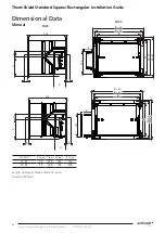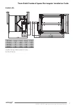
ThermShield Standard Square/Rectangular Installation Guide
28
Swegon reserves the right to alter specifications. 20210615 - L00010
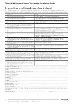
Inspection and handover check sheet
This certificate applies only to Swegon Fire Dampers. The installer must complete this installation certificate when
installing fire and smoke dampers. A separate certificate must be completed for each individual fire and smoke damper.
Damper Unique System I.D: ..........................................................................................................................................................
Name of installation location:.........................................................................................................................................................
Address:............................................................................................................................................................................................
Installation location identification section/floor/room: ................................................................................................................
Damper product type: ....................................................................................................................................................................
Release fuse temperature: ..............................................................................................................................................................
Notes/Considerations: ....................................................................................................................................................................
Installed by: .....................................................................................................................................................................................
Company Name: ............................................................................................................................................................................
Address: ..........................................................................................................................................................................................
Company Telephone No: ...............................................................................................................................................................
Installers Name: ..............................................................................................................................................................................
Installers Telephone No: .................................................................................................................................................................
Date of installation: ........................................................................................................................................................................
It is hereby verified that the damper detailed above has been installed and tested according to the manufactures recom
-
mendations:
Installers signature: ................................................................................................
Date: ................................................
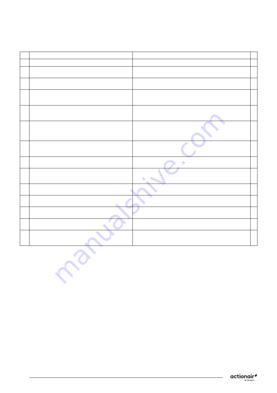
Question
Action
1
Are the dampers the correct type?
Confirm damper is correct type for the application
2
Are the dampers located correctly?
The damper location is to be checked against the installation
drawings/details
3
Are the dampers correctly identified?
Unique system ID to be clearly indicated on the damper or
other agreed location.
4
Have supports for both the damper and the adjacent
ductwork been installed in accordance with the
approved manner?
5
Are the dampers fitted in the correct orientation?
Confirm the damper is installed with any actuators (if
applicable) on the left or right hand side. Not on the top or the
bottom (i.e. blade pivot running vertically).
6
Is access through the ductwork, to the damper unob-
structed?
Unobstructed space should be provided for safe access to
the damper. This must include access through ceiling voids
and adjacent services. Damper installer to advise the system
designer if problems are foreseen.
7
Has the space around the damper and within the
opening been left clear and not been used for other
services?
Other services within the installation opening will invalidate
the installation method. Damper installer to advise the lead
contractor if problems are foreseen.
8
Using the access opening provided, check that blades
open and close.
Check position of damper blades.
9
Has the damper been checked for internal cleanliness,
free from damage and that vertical casings in particular
are free from debris?
With the damper in the closed position, inspect for damage.
10
Has the damper been released to simulate operation of
the thermal release? (Damper drop test)
Ensure damper operation is free from interference.
11
Have the damper blades been re-set following drop
test and the access panel replaced?
After re-setting the damper, check the position shown on the
blade position indicator is correct.
12
At the time of damper handover, is the fire barrier and
penetration seal complete?
Damper installer to record on the handover register if
any following trades are still to complete their activities.
13
Is the damper installation complete and available for
handover prior to system commissioning?
Obtain the relevant acceptance of the damper installation from
the CDM coordinator (or equivalent).
14
Is the completed handover register cross-referenced
back to the identification codes listed in the system
designers damper schedule?

