background image

4

Swegon reserves the right to alter specifications. 

20150225 

www.swegon.com

WISE

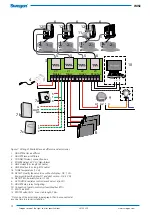
Figure 7. Wiring of Master/Slave air diffusers and accessories.

1.   ADAPT Master air diffuser 
2.   ADAPT Slave air diffusers 
3.   CONNECT Adapt, connection box 
4.   POWER Adapt, 24 V AC transformer 
5.   LINK Adapt (5 m long RJ45 cable) 
6.   LINK Modbus (5 m long RJ12 cable) 
7a.  TUNE Temperature (1 VA) 
7b.  DETECT Quality (Room version without display - Q0: 1 VA.  
 

Room version with display Q1 and duct version - Q2: 3 VA) 

7c.  DETECT RH, humidity sensor (1 VA) 
8.   ACTUATOR, radiator control (max 3 valves at 6 VA) 
9.   ADAPT Relay, relay for lighting 
10.  Connection to main control system (Modbus RTU) 
11.  SPLIT Link RJ45 
12.  SPLIT Modbus RJ12, max. stab length, 10 m.

*) 

Only one of the accessories in paragraph 7 can be connected at 

any one time in a room installation.

  20

Master

  21

Slave

  22

Slave

   23

Modbus

 1    2    3   4    5    6    7    8    9  10  11  12  13  14  15  16 

1

2

6

5

4

3

9

5

5

2

2

10

11

5

-  + C

A1  A2  1  3

12

6

8

5

1

6

7a

7b

G

G0

OUT1

1

2

3

7c

6

6

12

12

Summary of Contents for ADAPT Colibri d

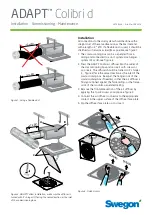
Page 1: ...s The diffuser should be turned so it s hinges C figure 2 face the same direction as the inlet of the commissioning box Readjust the hanger rods of the commissioning box if needed so that the air diffuser is firmly positioned against the false ceiling or the frame work of the modular suspended ceiling 3 Remove the frontplate section of the air diffuser by applying the Quick Access principle see fi...

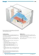
Page 2: ... orange The different LED indications Steady green LED Normal operation the air diffuser is operating normally Flashing green LED The air diffuser has just been powered on and calibration is in progress Steady red LED Function failure see separate docu mentation in the TUNE Adapt manual Steady orange LED The commissioning mode max airflow Flashing orange LED Other commissioning modes and all the f...

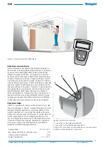
Page 3: ...f longer distances are required All cables and contacts are different so that they will not be confused or incorrectly connected Electrical data ADAPT is supplied with power via the connection box See the wiring diagram in figure 7 or relevant diagram from the Swegon Templates application containing details for the specific installation It is important that cables with appro priate cross sectional...

Page 4: ...m version without display Q0 1 VA Room version with display Q1 and duct version Q2 3 VA 7c DETECT RH humidity sensor 1 VA 8 ACTUATOR radiator control max 3 valves at 6 VA 9 ADAPT Relay relay for lighting 10 Connection to main control system Modbus RTU 11 SPLIT Link RJ45 12 SPLIT Modbus RJ12 max stab length 10 m Only one of the accessories in paragraph 7 can be connected at any one time in a room i...

Reviews: