background image

1

ADAPT

TM


Free d

Installation – Commissioning – Maintenance

20151013  /  Art. No. 1545217  

Installation

All connections to the duct system should be done with a 
straight duct of the same dimension as the box inlet and 
with a length > 2 x ØD. If a flexible duct is used, it should be 
stretched so it remains as straight as possible, see figure 1.
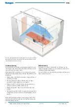
1. The commissioning box can be suspended from a ceiling 

and connected to a duct system.The diffuser is secured 
to the ceiling by connecting the M8 threaded rod (A) 
into the popnut on the top of the diffuser, see figure 3. 

2. Make sure that the orientation of the sensor module 

aligns with the extension of the room, see figure 2. If 
the connecting duct does not enter the room as in the 
example in figure 4, the frontplate of the diffuser must 

be dismantled and rotated in a direction with the sensor 
module directed as shown in figure 2. Then fixate and 
secure the diffuser with screws or pop rivets. Readjust 
the hanger rods of the commissioning box if necessary

3. The front plate is dismantled by pressing the fixing pins 

of the bottom plate outward, which will loosen it from 
the upper cone. Detach the safety cord that secures front 
plate to the upper cone and disconnect the connector 
(C, figure 3) from the top of the front plate. When reas-
sembling, press together the S-hook to prevent it from 
coming loose. 

A

B

C

Figure 3. ADAPT Free, installation.

Figure 2. The orientation of the sensor module in a room or in an 
office module. The LED’s of the sensor should be aligned with 
the extension of the room in a straight line, facing the short sides 
of the room as shown by the arrow in the figure.

Figure 1. Using a flexible duct.

Summary of Contents for ADAPT Free d

Page 1: ...n figure 4 the frontplate of the diffuser must be dismantled and rotated in a direction with the sensor module directed as shown in figure 2 Then fixate and secure the diffuser with screws or pop rivets Readjust the hanger rods of the commissioning box if necessary 3 The front plate is dismantled by pressing the fixing pins of the bottom plate outward which will loosen it from the upper cone Detac...

Page 2: ...es orange The different LED indications Steady green LED Normal operation the air diffuser is operating normally Flashing green LED The air diffuser has just been powered on and calibration is in progress Steady red LED Function failure see separate docu mentation inte the TUNE Adapt manual Steady orange LED The commissioning mode max airflow Flashing orange LED Other commissioning modes and all t...

Page 3: ...f longer distances are required All cables and contacts are different so that they will not be confused or incorrectly connected Electrical data ADAPT is supplied with power via the connection box See the wiring diagram in figure 7 or relevant diagram from the Swegon Templates application containing details for the specific installation It is important that cables with appro priate cross sectional...

Page 4: ... with display Q0 1 VA Room version without display Q1 and duct version Q2 3 VA 7c DETECT RH humidity sensor 1 VA 8 ACTUATOR radiator control max 3 valves at 6 VA 9 ADAPT Relay relay for lighting 10 Connection to main control system Modbus RTU 11 SPLIT Link RJ45 12 SPLIT Modbus RJ12 max stab length 10 m Only one of the accessories in paragraph 7 can be connected at any one time in a room installati...

Reviews: