background image

11

VAR

Swegon reserves the right to alter specifications. 

20111011 www.swegon.com

3,52 V

V DC

-

+

PP

Z1 Z2

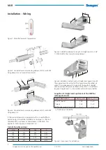
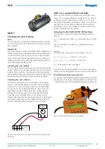
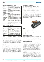
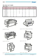
Figure 23. Shows how to connect a voltmeter for checking the 
true value.

Trouble shooting

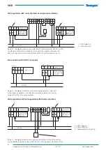
Incorrect polarity on control signal zero conductor

It is important that the neutral conductor follows the 
entire chain of connections from thermostat to control-
ler. Check this by measuring the control voltage between 
cables 1 and 3 on the VAR. Correctly wired it should be 
possible to vary the signal between 0.5-10 V DC.  If incor-
rectly wired the signal will be ~  8 - 14 V DC; for the RTC 
the signal will be ~ 2 - 8 V DC. 

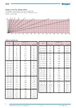
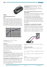
The airflow does not agree

This is almost always due to that the requirements for 
lengths of straight ducting upstream/downstream of the 
VAR have not been met. If the ducting deviates from these 
requirements, the error can be as much as 20%. The flow 
measurement sensor may become fouled in systems with 
considerable dusty air (most often extract air systems). This 
however doesn’t occur until the system has been operating 
for 3-5 years. The sensor can be cleaned by blowing it with 
clean air in the opposite direction, i.e. in the tube connec-
tion. We recommend compressed air in a low-pressure 
aerosol tube. The duct must also be cleaned so that the 
measurement flange and the pressure tappings are not 
clogged.

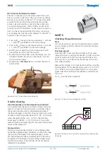
Changing the settings

The min./max. airflow values are calculated and set as 
follows: 

Q

max

 % required max. airflow (Q

max

) divided by nominal airflow 

(Q

nom

).

 
Q

min

 % required min. airflow (Q

min

) divided by nominal airflow 

(Q

nom

). 

Example: 
VAR, dim. Ø160, required min./max. airflows: 51/119 l/s.
Q

max

 % = Q

max

 / Q

nom

 =>119/170 = 0.70 = 70%

Q

min  

% = Q

min

 / Q

nom

 => 51/170   = 0.30 = 30%

Q

nom

  is read from Table 1 on page 9.


Enter the settings directly in the controller. No external 
instrument is needed but the settings can also be adjusted 
with Belimo’s instrument, ZTH-GEN.

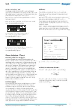
Configuration menu ZTH-GEN

Start:

Hold the (OK) button depressed and at the 
same time connect to the VAV controller.

HW Version 
SW Version

Indicates which hardware or software ver-
sion the unit runs

Reply:

"Configuration menu"appears in the display 
window 

Select setting

Press the 

 button (see selection below)

Choice of 
language

German

*

/English

Choice of unit

m

3

/h

 *, l/s, cfm

Voltage

DC/AC 24 V (shows current supply voltage)

MP test

Shows the pulse train in the network (for 
system integrator)

Expert mode

0 */ 1 (provides expanded access to settings)

Advanced 
mode

0 */ 1 (provides expanded access to settings)

Exit

Via menu selection (returns automatically to 
the mode for configuring the VAV controller) 
or for removing the connection to the VAV 
controller. The selected settings are automa-
tically stored in the ZTH.

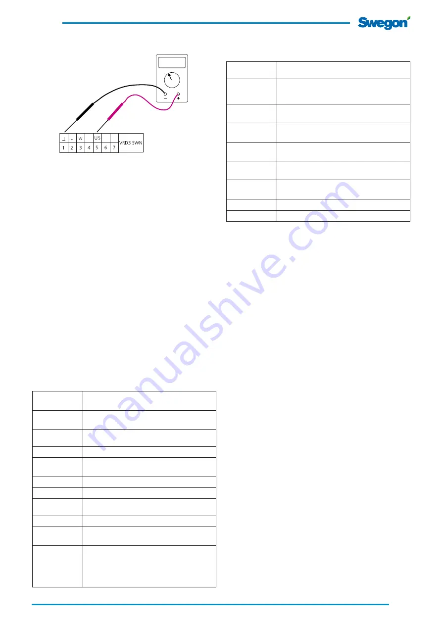
Start menu of the VAV controller

VRD3 SWN

Indicates to which controller the ZTH-GEN is 
connected.

Volume 0%      
Setpoint 0%

Shows the true value in % of the nominal fl
ow                                Shows the calculated 
set point

Volume 0% 
Pressure 0Pa

Shows  the  true  value  in  %  of  the  nominal  flow                                 
Shows the manometer pressure in Pa

Volume 0% 
CAV-Step

Shows the true value as a percentage of the 
nominal  

Auto

, Open, Close, Vmax, Vmin, Stop

Mode 0.0-10.0 
-new:

Shows the current operating range for control 
signalRange for control signal 0-10V or 2-10 V

Vmin         
-new

Set point for min. flow in % 
Set point (potentiometer in tool area)

Vmax         
-new

Set point for max. flow in %  
Set point (potentiometer in tool area)

Vnom

Shows nominal flow in %

p@Vnom

Shows nominal flow in Pa

Summary of Contents for BELIMO ZTH-GEN

Page 1: ...ce 20111011 Contents Installation Wiring guides Pages 2 7 Commissioning Flows Pages 7 8 How to use the VAR 1 Pages 9 10 How to use the VAR 2 Pages 10 11 How to use the VAR 4 Pages 12 13 How to use the VAR 5 Page 13 Dimensions and weights Page 14 ...

Page 2: ... mm length of straight duct 2 Sound attenuator with sound baffles Figure 4 Installation demands a length of straight duct A 2 x B 1 VAR Variable flow commissioning damper Figure 2 Variable flow commissioning damper VAR 1 with FSR fixing clamp 2 and sound attenuator 3 If the sound attenuator is equipped with a sound baffle or centre body it should be installed at a distance 2 x the duct diameter ØD...

Page 3: ... airflow Wiring diagrams Figure 8 Wiring diagram for VAR 2 Figure 7 Wiring diagram for VAR 1 Colour codes 1 Black 2 Red 3 and 5 White Insulate any conductors not in use VAR 1 Belimo compact Supply voltage 24 V AC 20 50 60 Hz Supply voltage 24 V DC 10 Controller and motor 6 VA Input 3 resistance 100 kOhm Input 3 control signal 0 10 alt 2 10 V DC Output 5 true value 2 10 V DC max 0 6 mA Ambient air ...

Page 4: ...SWN LMV D3 MP SWN NMV D3 MP SWN VRD3 SWN VAR VAR LMV D3 MP SWN NMV D3 MP SWN VRD3 SWN LMV D3 MP SWN NMV D3 MP SWN VRD3 SWN VAR VAR RTC RTCT Room thermostat Figure 10 The diagram shows how to wire the VART room ther mostat with simultaneous control of the extract air The figure also shows an alternative with RTCT duct temperature sensor 1 VAR Supply air 2 VAR Extract air CO2 and temperature control...

Page 5: ...mo Compact 1 VAR Supply air 2 VAR Extract air Y LMV D3 MP SWN NMV D3 MP SWN LMV D3 MP SWN NMV D3 MP SWN DETECT O VAR VAR Y U U DETECT O VAR VAR Figure 14 Wiring diagram VAR 4 Siemens 1 VAR Supply air 2 VAR Extract air VRD2 Ser Actuator VRD3 Figure 13b Jumper configuration VAR 2 Belimo Universal VRD2 DETECT O controls to fully open damper VRD3 DETECT O controls to preset flow for V max Figure 13a W...

Page 6: ...th VART 5 as master Figure 16 The diagram shows the connections between master slave unit In this wiring configuration the VAR slave controller should be set to a flow range of 0 100 of the nominal airflow 1 VAR Supply air 2 VAR Extract air LMV D3 MP SWN NMV D3 MP SWN VRD3 SWN LMV D3 MP SWN NMV D3 MP SWN VRD3 SWN DETECT O VAR VAR RTC VAV regulation with room thermostat and presence detector 1 VAR ...

Page 7: ...direction should always be such that the damper is fitted down stream of the flow measuring device The unit s rating plate includes air direction arrows Control signals All the electronic VAR devices are designed for a signal range of 0 10V DC Any deviation from this range is indicated on the product rating plate If a direct wired room thermostat is used for controlling the airflow requirements th...

Page 8: ... 5Pa Qnom max 120Pa K factor 1000 x 400 762 3735 341 0 1200 x 400 915 4480 409 0 1400 x 400 1069 5236 478 0 1600 x 400 1221 5981 546 0 500 x 500 479 2344 214 0 600 x 500 575 2815 257 0 700 x 500 671 3286 300 0 800 x 500 767 3757 343 0 1000 x 500 959 4699 429 0 1200 x 500 1149 5631 514 0 1400 x 500 1342 6573 600 0 1600 x 500 1534 7515 686 0 600 x 600 691 3385 309 0 700 x 600 807 3955 361 0 800 x 60...

Page 9: ...r If this is not done you will destroy the output on the control equipment The damper will move to the open position Measure the voltage U and calculate the airflow using Formula 2 on page 7 Figure 21 Shows how to connect a voltmeter for checking the true value Figur 22 ZTH GEN hand held micro terminal VAR 1 as a constant flow controller VAR 1 can be used as a constant flow controller in two ways ...

Page 10: ...u of the VAV controller Start Connect the cable provided to the VAV controller Reply The type of controller connected appears in the display window OK button The serial number of the controller is shown button The program version of the controller is shown Select fun ction Navigate forward backward to scroll between the various menu positions see table below Exit Disconnect the cable to the VAV co...

Page 11: ...s 51 119 l s Qmax Qmax Qnom 119 170 0 70 70 Qmin Qmin Qnom 51 170 0 30 30 Qnom is read from Table 1 on page 9 Enter the settings directly in the controller No external instrument is needed but the settings can also be adjusted with Belimo s instrument ZTH GEN Configuration menu ZTH GEN Start Hold the OK button depressed and at the same time connect to the VAV controller HW Version SW Version Indic...

Page 12: ...he controller will lose its positioning capability and you will have to de energize the unit for at least five seconds to remedy the situation If you want to test or force the commissioning damper use the jumper connections shown below or use the AST 10 hand held micro terminal Checking the min flow If possible zero volt is transmitted from the room unit or the main control system If this possibil...

Page 13: ...n nect it to the same terminal that the motor conductors are connected to See the wiring diagram for the AST 10 supplied in the instrument case 1 Press on Vmax change to the required value with the buttons press SET to confirm the change 2 Press on Vmin change to the required value with the buttons press SET to confirm the change 3 With Y you can read the control voltage set point transmitted from...

Page 14: ...1 2 6 3 9 125 124 472 245 61 77 180 401 2 9 4 0 160 159 472 285 61 60 215 401 3 3 4 8 200 199 472 335 61 40 255 401 4 0 5 8 250 249 522 395 61 15 305 452 4 9 7 8 315 314 552 465 61 370 452 6 5 9 7 400 399 684 553 61 462 614 10 7 14 9 500 499 810 653 61 565 740 15 7 21 3 250 Figure 34 VART 5 rectangular Figure 33 VAR 4 circular Figure 32 VAR 1 IR rectangular insulated casing Figure 31 VART 5 circul...

Reviews: