
7
VAR
Swegon reserves the right to alter specifications.
20111011 www.swegon.com
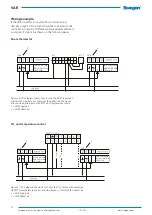
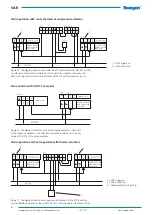
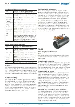
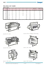
Jumper connection - RTC
The jumper connection in the RTC must be changed
when you wire the thermo-actuator (3) to the system. See
the figures below. A maximum of 4 thermo-actuators are
permitted to be wired to the same output.
N.B.! The unit must be de-energized before you recon-
nect any jumpers!
More information on the RTC can be read in its Installa-
tion – Commissioning Instructions.
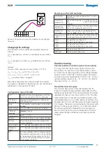
Figure 19. Jumper connection for thermo-actuator, heat.
YK = Cooling energy regulation: 0-10V DC
YH = Heat regulation: 024V DC
Figure 18. Jumper connection, Delivery settings.
YK = Cooling energy regulation: 0-10V DC
YH = Heat regulation: 0-10V DC
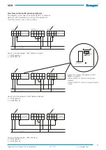
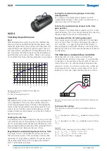
Nom flow = 170 l/s
VARd 1-160
k-factor = 15,5
170 l/s
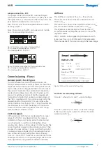
Commissioning - Flows
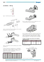
General points for all types
The VAR variable-flow commissioning dampers are
factory-calibrated and are normally preset for the airflow
range specified for the project. The setting values can be
read on the product rating plate affixed on both sides of
the product. Installation info and electrical connections
are described in these instructions. For the best perfor-
mance, it is extremely important that the requirement
for lengths of straight duct upstream or downstream of
the VAR is complied with. If you arrange only half of the
required length of straight duct, this may increase the
control tolerance from 5 up to 20%. The airflow direction
should always be such that the damper is fitted down-
stream of the flow measuring device. The unit’s rating
plate includes air direction arrows.
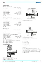
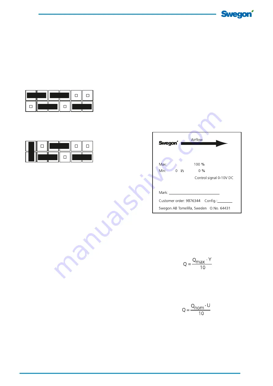
Control signals
All the electronic VAR devices are designed for a signal
range of 0-10V DC. Any deviation from this range is
indicated on the product rating plate. If a direct-wired
room thermostat is used for controlling the airflow
requirements, then a control voltage of <0.5V implies the
min. airflow that is preset in the controller and 10 V then
produces the max. airflow. It is common that the control
is carried out via a controller that then manages the min./
max. airflow setting by limiting the control signal e.g.
from 2.3 – 7.6 Volt DC. If wired to a controller, the VAR is
normally set to 0-100% of its operating range. N.B. In some
cases, high airflows can generate increased sound levels.
Figure 20. Shows the product rating plate.
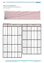
Formulas for calculating airflows.
Formula 1, where Q = l/s and Y = control voltage.
Formula 2, where Q = l/s and U = true value voltage.
If the true value signal is used, the airflow should be
worked out with Q
nom.
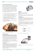
Airflows
The VAR has a nominal air flow, Q
nom
for each size.
The maximum air flow can be set to between 30 and
100% of Q
nom
.
The minimum air flow can be adjusted in relation to Q
nom
and can be set to between 0 and 100% of Q
nom
.
The regulators cannot manage air flows less than Q
min
,
as the manometer reading then becomes too low and
regulation ceases.
VAR 1, 2 and 4 can be supplied in special versions with
larger max. flow, up to 200 Pa read on the manometer.
The consequence of this is less accuracy in the lower range.


