
8
VAR
Swegon reserves the right to alter specifications.
20111011
www.swegon.com
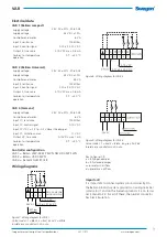
Airflow and K-factor
Size
Airflows (l/s)
Qmin (5Pa)
Qnom/max (120Pa)
K-factor
100
12
58
5.3
125
19
95
8.7
160
35
170
15.5
200
55
272
24.8
250
89
438
40.0
315
142
695
63.4
400
228
1117
102.0
500
367
1797
164.0
200 x 200
75
367
33.5
300 x 200
112
548
50.0
400 x 200
149
728
66.5
500 x 200
187
915
83.5
600 x 200
224
1095
100.0
700 x 200
262
1282
117.0
800 x 200
297
4157
133.0
1000 x 200
373
1829
167.0
300 x 300
170
833
76.0
400 x 300
228
1117
102.0
500 x 300
284
1391
127.0
600 x 300
340
1665
152.0
700 x 300
398
1950
178.0
800 x 300
454
2224
203.0
1000 x 300
568
2782
254.0
400 x 400
304
1490
136.0
500 x 400
382
1873
171.0
600 x 400
458
2246
205.0
700 x 400
534
2618
239.0
800 x 400
610
2991
273.0
Size
Airflows (l/s)
Qmin (5Pa)
Qnom/max (120Pa)
K-factor
1000 x 400
762
3735
341.0
1200 x 400
915
4480
409.0
1400 x 400
1069
5236
478.0
1600 x 400
1221
5981
546.0
500 x 500
479
2344
214.0
600 x 500
575
2815
257.0
700 x 500
671
3286
300.0
800 x 500
767
3757
343.0
1000 x 500
959
4699
429.0
1200 x 500
1149
5631
514.0
1400 x 500
1342
6573
600.0
1600 x 500
1534
7515
686.0
600 x 600
691
3385
309.0
700 x 600
807
3955
361.0
800 x 600
921
4513
412.0
1000 x 600
1152
5642
515.0
1200 x 600
1382
6770
618.0
1400 x 600
1614
7909
722.0
1600 x 600
1845
9037
825.0
700 x 700
944
4623
422.0
800 x 700
1078
5280
482.0
1000 x 700
1348
6606
603.0
1200 x 700
1617
7920
723.0
1400 x 700
1887
9246
844.0
1600 x 700
2156
10560
964.0
1600
1500
1400
1300
1200
1100
1000
900
800
600
700
400
500
200
300
0
100
2
6
4
10
8
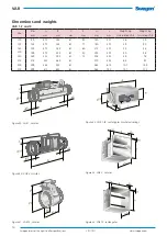
U Volt
l/s
Ø500
Ø400
Ø315
Ø250
Ø200
Ø160
Ø125
Ø100
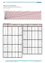
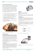
Diagram, true value voltage/airflow
The diagram is applicable only to factory-calibrated
products for nominal airflow according to the Airflow and
K-factor (COP) Table.


