13
W5
Smart
All rights to changes reserved.
2020-11-19
19. RH AI*
20. CO
2
AI*
21. VOC AI*
*) See the instruction supplied with the optional
equipment.
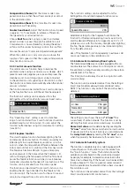
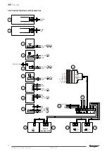
3.2.3 Relay outputs (DO)
The IO connections can be used for relay control
(24 VDC). See the connection instructions in the section
“Technical data”.
As relay outputs you can select:
22. Alarms
23. Duct damper
24. Away
25. Boost
26. Modbus*
27. DI control The position of the output is controlled by
relay control DI.
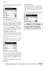
Important
The control card can be damaged if you
short-circuit the I/O-connection selected by
the relay output.
!
!
3.2.4 Control outputs (SEC/SEM – AO4)
The ventilation unit’s operating mode can be read as a
voltage signal on the AO4 output. If the ventilation unit
is controlled variably with Smart functions, the actual
value is regulated between the voltages 2 – 5 – 8 V.
Actual value for the fan speed 0-10 VDC
0 V = Not DDC control
1 V = Travelling
2 V = Away
5 V = Home
8 V = Boost
10 V = Stopped
heater is performed to the SET expansion module, ac-
cording to the instruction supplied with the accessory.
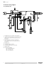
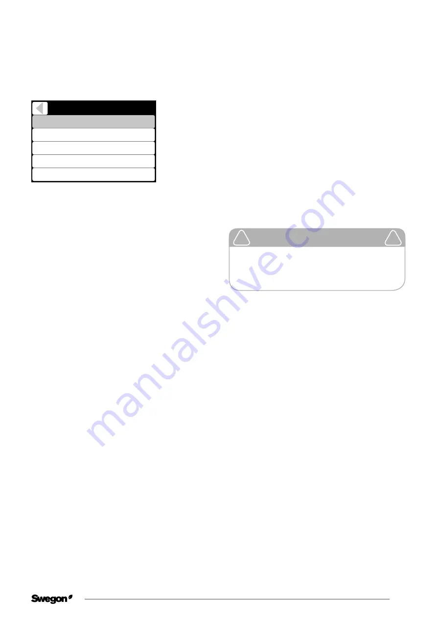
When you connect external equipment to the venti-
lation unit, the function of I/O connections must be
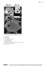
defined in the
menu “Setting/IO-control”
(the standard
option is shown in the figure).
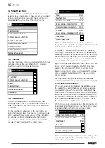
IO controls
IO 1
IO 2
IO 3 (ext.)
IO 4 (ext.)
Boost - DI
Away - DI
Emg.Stop_NO - DI
Fireplace - DI
IO 5 (ext.)
DDC control - AI
3.2.1 Digital switch input (DI)
Switch input options are:
1. Emg. Stop NC
2. Emg. Stop NO
3. Stop
4. Fireplace
5. Cooker hood
6. Central vacuum
7. Forced boost
8. Away
9. Boost
10. Modbus (not priority)
11. Relay control (not priority)
The priority of the selected inputs is determined accord-
ing to the previous list, so that a function that is higher
on the list has a higher priority than those below.
3.2.2 Control inputs (AI)
12. By selecting DDC - AI, the ventilation unit’s operat-
ing mode can be controlled by a voltage signal.
Operating mode control 0–10 VDC (+/- 0.5 V)
0 V = Not DDC control
1 V = Travelling
2 V = Away
5 V = Home
8 V = Boost
10 V = Stopped
13. Variable control occurs between the voltages 2 V
– 5 V – 8 V. The ventilation then switches variably
between operating modes Away - Home - Boost.
Otherwise, control is performed according to the
normal DDC control.
14. Modbus AI*
15. PA supply air*
16. PA extract air
17. l/s (supply air)*
18. l/s (extract air)*


