background image

W5 

Smart

18

All rights to changes reserved.

2020-11-19

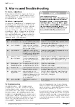
Important

The ventilation unit must not be operated  
without filters! Use only filters recom-
mended by Swegon in the ventilation unit. 
Find the correct filter in the Section enti-
tled: ”Technical data”.

!

!

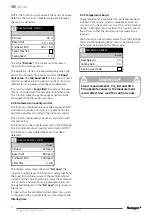
4.1 Service reminder

The service reminder is activated with preset time inter-
vals and the  symbol is displayed on the control panel’s 
screen. As a factory setting, the service reminder is not 
in operation. It can be put into operation under the 
main menu item “Diagnostics”/”Service reminder”. The 
recommended service interval for the ventilation unit is 
six months.

When servicing has been performed, the service remind-
er is reset from “Alarm” in the main menu.

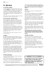
4.2 To open the ventilation unit

Before you begin any service work, isolate the power 
supply voltage to the ventilation unit by pulling out its 
electric plug from the wall socket. Wait a few minutes 
before you open the inspection door of the ventilation 
unit so that the fans have time to stop and possible air 
heaters have time to cool down.

The inspection door can be opened by turning the lock 
bolt with a screw driver for slotted screw heads. Support 
the top edge of the door with one hand when you open 
the lock bolt. Tilt the top edge outwards, towards you, 
and then lift the door away from its place. The door 
weighs about 11 kg.

Turn the service switch to the 0-position prior to com-
mencing servicing.

4.3 Filter

The filters should be replaced at least every six months. 
The filters may need to be cleaned or replaced more often 
in homes where there is considerable dust or if there are 
many impurities in the outdoor air. 

In a new home, there is still moisture from the construc-
tion period, and the filters can become soiled more quickly 
than usual. The first filter change should therefore be 
made approximately three months after the ventilation unit 
was commissioned.

The ventilation unit must not be operated without filters. 
Use only filters recommended by Swegon in the ventila-
tion unit. This is important, as filters with exactly the same 
appearance and size can have very different pressure losses 
and filter capacity. If an incorrect filter is used, it is not cer-
tain that the ventilation unit will work as designed. Check 
in the list of components that you have selected correct 
filters.

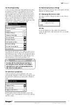
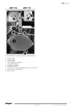
4.4 Heat exchanger

You should check the condition of the heat exchanger 
whenever you service the unit.

Pull out the heat exchanger’s sealing plate from the ven-
tilation unit. You can now pull out the heat exchanger 
for inspection. Do not damage the heat exchanger fins.

Make sure that the passages through the heat ex-
changer rotor are not clogged and clean them e.g. with 

4. Service

running warm water if required. Never use cleaning 
agents. 

The passages of the heat exchanger should 

be dry before you reinstall the heat exchanger in 
the unit.

4.5 Fans

The ventilation unit’s fans must be checked at least 
every two years. 

You must remove the preheater from the ventilation unit 
before the supply air fans are loosened. The preheater is 
secured in the ventilation unit with three screws. 

The fan packages are secured with four screws, placed 
in the corners of the mounting plate. When the screws 
are loosened, you can pull out the fan package from 
the ventilation unit. Exercise care not to damage the fan 
cables.

Clean the fans with a soft brush or cloth if necessary. Be 
careful not to dislocate the impeller balancing weights. 
If significant amounts of dirt collect on the fan impeller 
cleaning should be left to a professional.

The fans are reinstalled by sliding them back into place 
and tightening the screws in the corners of the mount-
ing plate. The preheater is refitted in position with three 
screws.

The ventilation unit’s fans must be loosened 
from their locations and protected, for example, 
with plastic bags, while the ventilation ducts are 
cleaned.

4.6 Other servicing

Clean the inner surfaces of the ventilation unit by 
vacuum cleaning or with a damp cloth, if needed.

Check that dirt has not collected on the surfaces of the 
air heater/coolers, clean if necessary.  

Check that the condensate discharge outlet is not 
clogged and check its outflow by pouring water on 
the bottom of the ventilation unit. The condensate 
discharge connection is located on the rear of the unit 
under the rotary heat exchanger.

Check that the ventilation unit works normally and that 
no alarms are shown on the screen or on the cooker 
hood. 

Summary of Contents for CASA SMART W9 Econo

Page 1: ...W5_e_EN t CASA W5 SMART Installation commissioning and maintenance instruction TECHNICAL MANUAL...

Page 2: ...l 16 3 3 9 Temperature boost 16 3 4 Heating cooling 17 3 5 Anti frost protection 17 3 6 Restoring factory settings 17 3 7 Changing the service code 17 3 8 Use 17 4 Service 18 4 1 Service reminder 18 4...

Page 3: ...ct so that the air heater cannot freeze during a power failure and unit freezing pro tection works correctly Condensation The surface temperature of the ventilation unit can drop down to low during pe...

Page 4: ...lass ISO ePM1 50 F7 and with extract air filter according to filter class ISO coarse G3 The need of filter replacement is indicated on the con trol panel and on a CASA Smart cooker hood 1 4 Heat excha...

Page 5: ...s and feel a click the overtemperature protection thermal overload cut out has then been reset Ventilation unit with water heated air heater The ventilation unit with water heated air heater has a tem...

Page 6: ...ntilation unit on a wall by means of a wall mounting bracket which is included in the delivery If the wall is composed of vertical studs and wall boards the wall must be reinforced with horizontal stu...

Page 7: ...bles through the ceiling mounting frame To make it easier to lift the ventilation unit the inspec tion cover can be removed and the heat exchanger can be dismantled from the unit See the Servicing Sec...

Page 8: ...sory P05PP for sealing the vapour barrier in the loft ceiling beams Cut up the openings with approx 10 mm smaller diam eter than that of the ducts Secure the mounting frame in the ceiling with screws...

Page 9: ...accessories are not included in the supply In general ventilation ducts should be insulated in the following manner Insulate outdoor air ducts run through warm spaces Exhaust air ducts should always...

Page 10: ...ntrol panel can be mounted up to 40 metres from the unit using 2 x 20 metre long modular cables The front panel on the Smart control panel is released using a screwdriver to push the retaining clips t...

Page 11: ...11 W5 Smart All rights to changes reserved 2020 11 19...

Page 12: ...ilation unit s fans run at the speed being set and functions that can disrupt the setting such as anti freeze protection are disabled Airflow adjustments Commissioning mode Home exhaust Away supply Aw...

Page 13: ...ccessory When you connect external equipment to the venti lation unit the function of I O connections must be defined in the menu Setting IO control the standard option is shown in the figure IO contr...

Page 14: ...d defined I O input IO control receives the signal and runs until the damper is closed The function is put into service from the Settings Smart functions Cooker hood boost menu The settings menu is op...

Page 15: ...m pensation value so that the air flows are kept as set out in the ventilation plan Compensation boost Fine tune Boost mode s com pensation value if necessary Cooker hood boost Adjust the function s b...

Page 16: ...rom the Settings Smart Functions Auto air quality control menu NOTE The function is only visible if the sensor has been detected Auto Air Quality control Mode Boost limit Full boost limit 1400 ppm 800...

Page 17: ...functions menu if the room temperature that is measured with a separate thermometer deviates from the temperature shown by the ventilation unit Important Turning off the internal post heating or lower...

Page 18: ...ses and filter capacity If an incorrect filter is used it is not cer tain that the ventilation unit will work as designed Check in the list of components that you have selected correct filters 4 4 Hea...

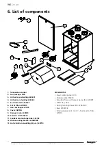
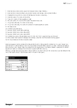
Page 19: ...Extract air filter 3 Heat exchanger 4 Heat exchanger s sealing plate 5 Condensate discharge 6 Air heater pre heating 7 Air heater reheating 8 Supply air fan s mounting plate behind the air heater pack...

Page 20: ...eating coil is too high Control air heater fault or overtempera ture protection has tripped Contact a service company Check the function of the air heater for preheating Freeze risk water heated air h...

Page 21: ...unit so that no uninsulated surface is visible Even a small gap in the insulation could cause among others condensation and acoustic problems 2 Make sure that the pipes connections to the ventilation...

Page 22: ...changer 61035 8 Cover DW5RL 9 Damper motor 60348 10 Service switch 50319 11 Condensate discharge tube 502103 12 Wall mounting bracket W05WMB 13 Anti vibration mountings 2 pcs 60790 Accessories Smart c...

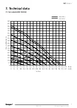
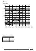
Page 23: ...essure differential Pa Supply airflow Extract airflow 0 50 100 150 200 250 300 350 400 450 500 550 600 650 700 750 800 850 900 0 10 20 30 40 50 60 70 80 90 100 110 120 130 140 150 160 170 l s 100 90 8...

Page 24: ...ans 238 W Air heater pre heating 1500 W Air heater reheating 500 W Total output 2248 W Power consumption 0 50 100 150 200 250 300 0 10 20 30 40 50 60 70 80 90 100 110 120 130 140 150 160 170 100 90 80...

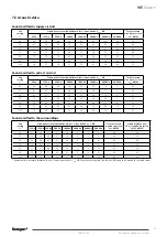
Page 25: ...54 46 27 26 15 0 48 60 67 57 57 50 31 29 18 2 51 70 72 61 62 55 35 34 23 7 56 80 74 63 64 57 37 36 25 9 58 90 75 65 65 58 39 37 26 10 59 100 76 66 67 59 40 38 28 11 61 Sound emitted to supply air duc...

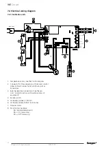
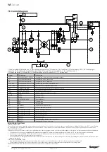
Page 26: ...od which are sold as accessories 3 External electrical connections See the sec tion Control functions with optional items of equipment 4 Service switch 5 Air heater preheat 1 500 W 6 Air heater reheat...

Page 27: ...27 W5 Smart All rights to changes reserved 2020 11 19...

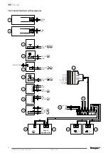
Page 28: ...ATION BUS TERMINATION 3 IO 3 4 IO 4 5 IO 5 6 DDC Out 7 5 V Out 8 GND SEC 16 15 14 3 102TKC 2 x 0 5 IO1 IO5 GND 4 2 1 3 117KHH 2 x 0 5 IO1 IO5 GND 5 1 NC 2 3 NO L N 230V AC 50Hz 105A1 2 x 0 5 2 x 1 5 I...

Page 29: ...ion points on the ventilation unit IO1 IO2 24 V 5 V selection from circuit board 15 SET module Smart Extension Temperature module connection card for external duct equipment 16 SEC Smart Extension Cab...

Page 30: ...matic defrost system that prevents the heat exchanger from freezing by enabling the preheater and if necessary by chan ging the fan speed IF THE SAFETY EQUIPMENT TRIPS If an overheating protection wit...

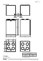
Page 31: ...0 168 432 630 73 72 951 993 597 630 1 2 3 4 5 1 2 3 4 73 72 5 Duct connections 1 2 3 4 Supply air 160 Extract 160 Outdoor air 160 Exhaust air 160 5 Condensate connection 7 6 Dimensions Left hand model...

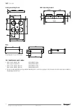
Page 32: ...W5 Smart R 500 W RH CO2 W05VR05S10CAA W5 Smart R 500 W RH CO2 W05VL05S10CAA Econo model available by using external heating duct coil in the supply air duct Sensors and actuator are included in the d...

Page 33: ...frame R L W05CMB Base W05FMB Water trap UVL Air cooler for cooling the supply air For 160 mm ducts SDCW 160W For 200 mm ducts SDCW 200W For 250 mm ducts SDCW 250F Air heater for heating the supply air...

Page 34: ...change 0 Cooker hood function boost of cooker hood 0 Fahood function operation of roof fan Not used Central vacuum function compensation 20 Air flows NOTE All the fan modes should be preset Project pl...

Page 35: ...35 W5 Smart All rights to changes reserved 2020 11 19...

Page 36: ...viceportal swegon com fi docs TM_W5_SE Installasjons igangkj rings og vedlikeholdsveiledning https serviceportal swegon com fi docs TM_W5_NO Installations Inbetriebnahme und Wartungsanleitung https se...

Reviews: