20
W100B.021014
Swegon reserves the right to alter specifications.
www.swegon.com/casa
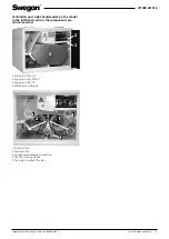
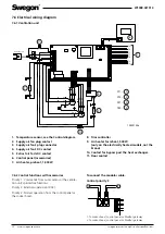
7.6 Electrical wiring diagram
7.6.1 Ventilation unit
1. Temperature sensor, see the Control diagram
2. Supply air fan plug contact
3. Supply air fan’s plug connector
4. Supply air fan’s DC contact
5. Extract air fan’s DC contact
6. Control panel (accessories)
7. Air heater, preheat, 1,000 W
8. Triac controller
9. Air heater for reheat, 500 W
(only on the electrically heated models, not the
Econo)
10. Contact for bypass past the heat exchanger.
11. Door contact
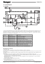
7.6.2 Control functions with accessories
Priority 1: Commands from outer sensor or the ventila-
tion unit’s protective functions.
Priority 2: External supervision (DDC).
Priority 3: Normal operation from the control panel or
the cooker hood.
To connect the modular cable.
Control priority 3
1. To cooker hood, control panel or Modbus gateway
2. To cooker hood, control panel or Modbus gateway
1
2
RESET
ELECTRIC
AFTERHEAT
EXHAUST
SUPPLY
14
13
24
23
S1
X11 N
RU
SI
X11 2
SI
KE
VA
X12 N
SI
X12 2
KE
VA
CO2 INPUT
%RH INPUT
TEMP INPUT
EC
EC
va
st
us
X21,
X2
1,
2
X2
1,
1
X
22, X2
2,
1
X2
2,
2
1000
W
1S000192d
14
13
S2
Input 230V 10A
T8
T4
T1
T7
T6
T3
T2
X11 -
X12 -
X21 -
X22 -
2
3
4
5
6
7
8
9
10
11
1

